|
There are currently no product reviews.
 ;
I wished detailed information of the JBL S310 and here I found it! Very happy with the service from this site!
;
The manual was very helpfull, it answerdes all my questions, and i was surprized to find the original manual on this site! Big thumbs uP:)
 ;
helpful manual.good service.Quick response.will use again
;
Speedy confirmation to my order , with elaborate instructions .
Item Email , received immediately as desired by me.
A Pleasant & Satisfying Transaction.
;
I was searching for this manual at last i got it from this web
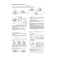
SECTION 3 ELECTRICAL ADJUSTMENT
Bias Adjustment
Note : The Bias adjustment should be performed only if any of Q108 to Q113 and Q208 to Q213 are replaced. Setting :
B+,REM terminal
set Stabilized Power suppy GND terminal
Procedure : 1. Rotate the variable resistors RV105 and RV205 fully in the clockwise direction to minimize the idling current of the stabilized power supply. 2. The input signal is to be no signal. 3. Set the power voltage to +14.4 V, and turn the remote mode ON (Connect between the REM terminal and B+ terminal). 4. Adjust each of RV105 and RV205 so that the power current of the stabilized power supply is increased in steps of 500 mA for the XM-1502SX and in steps of 600 mA for the XM-1902GX. Adjustment Location : Main board (component side)
� MAIN BOARD (COMPONENT SIDE) �
RV105 BIAS ADJUSTMENT
RV205 BIAS ADJUSTMENT
8
|