|
There are currently no product reviews.
 ;
I am a vintage hifi collector. No way to fix that device without the appropriate service manual...thanks to your site I got it and every thing is easier now. I got the manual right after ordering: fast cheap accurate ... thank you
;
Wonderful job clear. Qick fantastic. These people are really good. If even a problem arise they are wonderful assisting you. These scheme is so net despite this is a very old TV. Thank you for everything!!!!!!!!
;
Detailed schematic diagram, manual for professionals
;
Good service manual,exploded view,adjusment and test point locations,head alignment,mechanical checks and adjusments,all perfect.
;
Block diagram,play rec block diagram,adjusments, it's a very good well done repair manual.
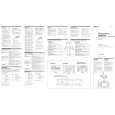
SECTION 3 ELECTRICAL ADJUSTMENT
Bias Adjustment
Note : The Bias adjustment should be performed only if any of Q108 to Q113 and Q208 to Q213 are replaced. Setting :
B+,REM terminal
set Stabilized Power suppy GND terminal
Procedure : 1. Rotate the variable resistors RV105 and RV205 fully in the clockwise direction to minimize the idling current of the stabilized power supply. 2. The input signal is to be no signal. 3. Set the power voltage to +14.4 V, and turn the remote mode ON (Connect between the REM terminal and B+ terminal). 4. Adjust each of RV105 and RV205 so that the power current of the stabilized power supply is increased in steps of 500 mA for the XM-1502SX and in steps of 600 mA for the XM-1902GX. Adjustment Location : Main board (component side)
� MAIN BOARD (COMPONENT SIDE) �
RV105 BIAS ADJUSTMENT
RV205 BIAS ADJUSTMENT
8
|