|
|
|
Categories
|
|
Information
|
|
Featured Product
|
|
|
 |
|
|
There are currently no product reviews.
 ;
I'm quite impressed. I had to wait 24 hours for my manual (quite a rare one) but I got it and the quality was good. Also, from trawling the web, these prices are by far the best.
;
Manuale perfetto. Ottimo e utilissimo. Grazie a questo manuale ho potuto realmente risolvere il complesso problema della stampante.
;
Manuale perfetto. Ottimo e utilissimo. Grazie a questo manuale ho potuto realmente risolvere il complesso problema della stampante.
 ;
Was very fast and accurate service. Just what I needed. I recommend to everyone.
;
Very good scan quality, only PC Board scan not enough contrast.
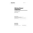
SECTION 3 DIAGRAMS
3-1. BLOCK DIAGRAM
CNJ101 (4/4) OUTPUT (THROUGH) L INPUT (MONO) CNJ101 (3/4) CNJ301(4P) L HIGH LEVEL INPUT R PRE AMP IC101(1/2) INPUT CNJ101 (2/4) OUTPUT (THROUGH) SW501 TEST TONE OP AMP 3 2 +B OP AMP 5 6 R 7 VR101 FILTER VR101(1/4),VR101(2/4) 5 LPF IC201(1/2) LPF 7 OFF SW501 FILTER 5 FILTER IC301(1/2) 7 VR102 LEVEL VR102(1/2) SWITCH Q301 DIFFERENTIAL AMP Q303 DRIVE AMP Q304 BIAS Q306,307 DIFFERENTIAL AMP Q302 6 5 DRIVE AMP Q305 DRIVE AMP Q309 POWER AMP Q311 OVER LOAD DET Q312 DRIVE AMP Q308 POWER AMP Q310 L+R MONO 3 2 1 PRE AMP IC101(2/2) VR101 FILTER VR101(3/4),VR101(4/4) 3 LPF IC201(2/2) LPF 1 OFF BIAS Q406,407 DIFFERENTIAL AMP Q402 DRIVE AMP Q405 DRIVE AMP Q409 POWER AMP Q411 OVER LOAD DET Q412 L SW501 FILTER 3 FILTER IC301(2/2) 1 VR102 LEVEL VR102(2/2) DIFFERENTIAL AMP Q403 CN201 SPEAKER OUT SWITCH Q401 DRIVE AMP Q404 DRIVE AMP Q408 POWER AMP Q410
XM-255EX/255NX
THIS NOTE IS COMMON FOR PRINTED WIRING BOARDS AND SCHEMATIC DIAGRAMS. (In addition to this, the necessary note is printed in each block.) For schematic diagrams.
Note: � All capacitors are in µF unless otherwise noted. pF: µµF 50 WV or less are not indicated except for electrolytics and tantalums. � All resistors are in � and 1/4 W or less unless otherwise specified. � C : panel designation. � U : B+ Line. � Power voltage is dc 14.4V and fed with regulated dc power supply from ACC and BATT cords. � Voltages and waveforms are dc with respect to ground under no-signal conditions. no mark : POWER ON * : Impossible to measure � Voltage are taken with a VOM (Input impedance 10 M�). Voltage variations may be noted due to normal production tolerances. � Signal path. F : AUDIO
R
CNJ101 (1/4)
1
7
IC401 (1/2)
IC401 (2/2) LINE CONTROL Q941,942 PH901 DC DET
TH901
B+
For printed wiring boards.
PROTECT LATCH Q904,905 (CURRENT CHECK)
Note: � X : parts extracted from the component side.
PROTECT LATCH Q906,907 (CURRENT CHECK) D904 DRIVER Q946,949 CN101 +12V F901 (20A) B+ SWITCH Q901,902
OFFSET DET Q953-954
T901 DC-DC CONVERTER TRANSFORMER RECT D908,909 +REG Q944 B+ B+
ON/OFF DRIVE Q948
B� ON/OFF DRIVE Q947 -REG Q933 B�
REMOTE
LED DRIVE SWITCH Q909,910
LED DRIVE SWITCH Q911,913
LED DRIVE SWITCH Q914,915
TH902
POWER ON/OFF Q903
Q908 16 3 1 14 10 ON/OFF CONTROL 9
DC-DC CONVERTER CONTROL IC901
D905
D906
D907
OSC
VCC 12 B+
D905 OVER CURRENT
D906 OFFSET
D907 THERMAL
09
POWER/PROTECTOR � Signal path F : AUDIO
7
7
|
|
|
> |
|