|
|
|
Categories
|
|
Information
|
|
Featured Product
|
|
|
 |
|
|
There are currently no product reviews.
 ;
I am proud of you. In the future, I benefited from your services.
;
I found this manual to be complete in every detail. Besides the schematic it has a complete set of alignment instructions which are easy to understand. It also includes a complete parts list as well as an explanation of how the power supply and safety shutdown circuits operate. Even a schematic of the tuner is included.
 ;
The product was good and just what I needed, however I had moderate difficulty with the down load because the sight would not recognize my pass word. I was finally given a direct link to the manual and that worked.
;
Very quick and easy website to use and fast download of manual, quality of manual is excellent and will be pleased to use this service again in the future, thanks so much!
;
It is an very good and clear scanned service manual.
very recommended.
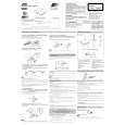
XM-PX5SL Removing the chassis ass�y (See Fig.5 and 6)
1. Remove the two screws B and the one screw C attaching the chassis assy. Remove the one screw D attaching the jack cover. 2. Open the battery lid and release the tab d from the battery contact. Pull out the battery lid. 3. Remove the one screw E attaching the arm (L). 4. Remove the chassis ass�y and the arm (L) while releasing them from the headphone jack on the bottom case.
Battery lid
B
Chassis ass'y
B
Bottom case
D C
Headphone jack Jack cover
Removing the main P.W. board and the battery holder(See Fig.7 and 8)
1. Use a soldering bit provided with ground to solder or unsolder the short round.
Fig.5
Headphone jack
2. Ground the set and the P.W.board. The voltage level of the ground should be equal to that of the soldering bit. 3. Prevent static electricity using an earth band, etc. 4. Solder the short round of the pickup FRC for short circuit. 5. Disconnect the flexible wires from the connector CN301 and CN801 on the main P.W.Board.
d Arm (L)
E
6. Remove the one screw F attaching the main P.W.board. Remove the main P.W.board and the battery holder, then reverse them. 7. Disconnect the flexible wire from connector CN601 on the main P.W.board.
Battery holder Soldering
Fig.6
8. Unsolder the soldered joint of the main P.W.board and the battery holder P.W.board.
Battery holder MD mechanism ass'y
F
CN401
Pickup short round CN601 Main P.W.board
CN301 Main P.W.board
Fig.8
Fig.7
1-6
 $4.99 XMPX5SL JVC
Owner's Manual Complete owner's manual in digital format. The manual will be available for download as PDF file aft…
|
|
|
> |
|