|
|
|
Categories
|
|
Information
|
|
Featured Product
|
|
|
 |
|
|
There are currently no product reviews.
 ;
The service manual is scanned, but high quality, high resolution. The smallest texts on schematics diagram is readable. Super! Thank you!
;
I am satisfied with the service. And if need another manual, i will definitely buy from this site. Keep up the good work.
;
have download a number of manuals todate , most are excellant, one or two sometimes a little difficult to read but a least avaialable, great site .
Brad.
;
Excellent had everything I wanted, very happy with purchase
 ;
This service is relatively cheap, document is fast available, schematic is readable.
Thanks.
XM-SD46X
Notes on Chip Component Replacement � Never reuse a disconnected chip component. � Notice that the minus side of a tantalum capacitor may be damaged by heat. UNLEADED SOLDER Boards requiring use of unleaded solder are printed with the lead free mark (LF) indicating the solder contains no lead. (Caution: Some printed circuit boards may not come printed with the lead free mark due to their particular size) : LEAD FREE MARK Unleaded solder has the following characteristics. � Unleaded solder melts at a temperature about 40 °C higher than ordinary solder. Ordinary soldering irons can be used but the iron tip has to be applied to the solder joint for a slightly longer time. Soldering irons using a temperature regulator should be set to about 350 °C. Caution: The printed pattern (copper foil) may peel away if the heated tip is applied for too long, so be careful! � Strong viscosity Unleaded solder is more viscou-s (sticky, less prone to flow) than ordinary solder so use caution not to let solder bridges occur such as on IC pins, etc. � Usable with ordinary solder It is best to use only unleaded solder but unleaded solder may also be added to ordinary solder.
TABLE OF CONTENTS 1. GENERAL
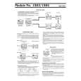
Location and Function of Controls .......................................... 3 Connections ............................................................................. 4
2. DISASSEMBLY
2-1. Bottom Plate ........................................................................ 6 2-2. Main Board Section ............................................................ 7 2-3. Main Board, Input Level Board .......................................... 7 2-4. LED Board .......................................................................... 8
3. ELECTRICAL ADJUSTMENT ...................................... 9 4. DIAGRAMS
4-1. 4-2. 4-3. 4-4. 4-5. Block Diagram .................................................................. 11 Printed Wiring Board �Main Section� .............................. 12 Schematic Diagram �Main Section (1/2)� ........................ 13 Schematic Diagram �Main Section (2/2)� ........................ 14 Printed Wiring Boards �Input Level, LED Section� ......... 15
5. EXPLODED VIEWS
5-1. Heat Sink (Main) Section .................................................. 16 5-2. Main Board Section .......................................................... 17
6. ELECTRICAL PARTS LIST ........................................ 18
SAFETY-RELATED COMPONENT WARNING!! COMPONENTS IDENTIFIED BY MARK 0 OR DOTTED LINE WITH MARK 0 ON THE SCHEMATIC DIAGRAMS AND IN THE PARTS LIST ARE CRITICAL TO SAFE OPERATION. REPLACE THESE COMPONENTS WITH SONY PARTS WHOSE PART NUMBERS APPEAR AS SHOWN IN THIS MANUAL OR IN SUPPLEMENTS PUBLISHED BY SONY.
ATTENTION AU COMPOSANT AYANT RAPPORT � LA S�CURIT�!! LES COMPOSANTS IDENTIFI�S PAR UNE MARQUE 0 SUR LES DIAGRAMMES SCH�MATIQUES ET LA LISTE DES PI�CES SONT CRITIQUES POUR LA S�CURIT� DE FONCTIONNEMENT. NE REMPLACER CES COMPOSANTS QUE PAR DES PI�CES SONY DONT LES NUM�ROS SONT DONN�S DANS CE MANUEL OU DANS LES SUPPL�MENTS PUBLI�S PAR SONY.
2
|
|
|
> |
|