|
|
|
Categories
|
|
Information
|
|
Featured Product
|
|
|
 |
|
|
There are currently no product reviews.
 ;
The schematic is very helpful and the images are very good.The schematic is very helpful and the images are very good.The schematic is very helpful and the images are very good.The schematic is very helpful and the images are very good.The schematic is very helpful and the images are very good.The schematic is very helpful and the images are very good.
;
Welcome. The scheme is clearly helped me to repair. Worth to download it.
 ;
Excellent manual, very clear, technical specification provided, useful information regarding adjustment and set up.
;
fast and easy and exactly what I was looking for. Not the cheapest but value for money after all.
;
The manual for the Sansui P-L75 was not one of the more informative turntable manuals around but for $5 it was helpful enough.
X-NM10, XR-NM1
Electrical Adjustment
Check the following before starting.
(1) Confirm that the tape speed adjustment has been completed. (2) Clean the heads and demagnetize them using a head eraser. (3) Set the measurement level to 0 dBV = 1 Vrms. (4) Use the specified tape for adjustment. Use the labeled (A) side of the test tape. NCT-132X : For playback check
Playback Adjustment
(1) Head Azimuth Adjustment
* When the tape is played with both of side panel L and R removed (state that reception front is floating from ground). when adjusting , the noise might be superimposed. In this case, the front chassis must short circuit to the CD mechanism cover in the lead wire.
Playback Adjustment
(1) Head Azimuth Adjustment
� Do not switch between forward and reverse operation with the screwdriver inserted.
Step Mode Input Signal/ Test Tape Adjusting Points Measurement Points Adjustment Value Remarks After adjustment, apply silicon bond to the head azimuth adjustment screw. SP OUT CN1 PB L ª ch Max. playback signal level PB R ªch
1
PLAY
N C T - 1 3 2 X t e s t t a p e Head azimuth adjustment (Playback: 10kHz, -20dB) screw (Fig. 4)
0 dB
30s 315 Hz
0 dB: 315 Hz, 250 nwb/m 30 s 6.3 kHz 30 s 10 kHz 30 s 315 Hz 10s .......................................................................................................... 10s �20 dB 12.5 6.3 500 250 125 14 kHz kHz 10 kHz 8 kHz kHz 4 kHz 2 kHz 1 kHz Hz Hz Hz 63 Hz 40 Hz 10s
Fig. 3 NCT-132X Test Tape
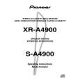
FWD Azimuth Adjustment Screw REV Azimuth Adjustment Screw
Fig. 4 Head Azimuth Adjustment
52
|
|
|
> |
|