|
|
|
Categories
|
|
Information
|
|
Featured Product
|
|
|
 |
|
|
There are currently no product reviews.
 ;
The manual you sent me was excellent. It included clear, readable diagrams and a usable parts list. I would surely use your service again. Thanks
;
Payments were processed quickly and items were exactly as described. I will use owner-manuals.com in the future for any other manual needs.
;
The Technics manual was very clear and I was able to solve my technical problems.
I did not think that anyone kept these manuals and was pleasantly surprised to find them on the Internet and at an affordable price.
I would recommend Owner Manuals as a first source of technical products for ‘dated’ equipment manuals.
Ian
;
The content of the manual was not found on the Internet and was a hard find. I check the net for 5 hours until I came across this web-site. When I did find the book it Auto loaded into my IPAD PDF shelf for books for review at anytime. Overall I am satisfied with the book and it answered all my questions. This repair book is obsolete because the product I bout it for is pretty old. Thanks for the help with the download and even having the manual. Thanks 73's K5HRD
;
Excellent manual including schematics. The service was great and the manual helped complete the job.
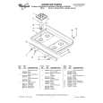
IC, MN662786SBM Pin No.
1 2 3 4 5 6 7 8 9 10 11 12 13 14 15 16 17 18 19 20 21 22 23 24 25 26 27 28 29 30 31 32 33 34 35 36 37 38 39 40 41
Pin Name
DRVDD D0 D1 NWE NRAS D2 D3 NCAS0 A10 A8 A7 A6 A5 A4 A9 A0 A1 A2 A3 DVSS2 DVDD2 SPOUT TRVP TRVM TRP TRM FOP FOM IOVDD1 TBAL FBAL FE TE RFENV OFT NRFDET BDO LDON ARF IREF ADPVCC
I/O
I I/O I/O O O I/O I/O O O O O O O O O O O O O I I O O O O O O O I O O I I I I I I O I I I
Description
DRAM interface power (terminal No. 2 to 19). DRAM data input/output signal 0. DRAM data input/output signal 1. DRAM write enable signal. DRAM RAS control signal. DRAM data input/output signal 2. DRAM data input/output signal 3. DRAM CAS control signal 0. DRAM address signal 10. DRAM address signal 8. DRAM address signal 7. DRAM address signal 6. DRAM address signal 5. DRAM address signal 4. DRAM address signal 9. DRAM address signal 0. DRAM address signal 1. DRAM address signal 2. DRAM address signal 3. Digital circuit GND. Digital circuit power. Spindle motor driver signal output. Traverse drive output (� polar output). Traverse drive output (+ polar output). Tracking drive output (� polar output). Tracking drive output (+ polar output). Focus drive output (� polar output). Focus drive output (+ polar output). I/O power supply. Tracking balance adjustment output. Focus balance adjustment output. Focus error signal input (analogue input). Tracking error signal input (analogue input). RF envelope signal input (analogue input). Off track signal input. "H": Off track. RF detection signal input. "L": Detected. Drop out signal input. "H": Drop out. Laser on signal output. "H": On. (Not used) RF signal input. Reference current input terminal. A/D reference voltage input (analogue input).
� 22 �
 $4.99 XPR232 AIWA
Owner's Manual Complete owner's manual in digital format. The manual will be available for download as PDF file aft…
|
|
|
> |
|