|
|
|
Categories
|
|
Information
|
|
Featured Product
|
|
|
 |
|
|
There are currently no product reviews.
 ;
Scan was really good quality, easy to read, download easy
;
very good manual as always. easy to read, detailed and includes schematic
;
I'm very satisfied with your manual service. Your website made it easy to locate the correct manual. Also the quality is great and I never had a problem reading the fine details.
Thanks again.
Jeff Miller
JM Electronics
 ;
Good quality service manual German user manual. German user manual This is a quality scan of a manual in excellent condition and is just as good as having the original manual in hand
;
The manual for Sony LBT-D505 component stereo system is was excellent , with schematics, parts layout and parts list as well as instructions for adjustments for each component. Print was clear even when enlarged.
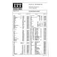
Pin No. 73 74 75 76 77
Pin Name VDD5V VSS CONT6 CONT7 V/*P
I/O � � I/O I/O O
Description Microprocessor interface power supply. (2000pF or more path controller to be inserted at a point nearer to the pin between this pin and GND) Digital ground pin. Must be connected to 0V. General-purpose input/output pin 6. General-pirpose input/output pin 7. Rough servo/phase control automatic switching monitor output pin. �H� for rough servo and �L� for phase servo. Synchronization signal detection output pin. Outputs a high level when the
78
FSEQ
O
synchronization signal detected from the EFM signal and the internally generated synchronization signal agree.
79 80
DEFECT EFMO
I/O O
Defect pin. Which becomes an input pin after reset and can be controlled externally. This becomes the defect monitor pin under control by command. EFM signal output pin.
18
|
|
|
> |
|