|
|
|
Categories
|
|
Information
|
|
Featured Product
|
|
|
 |
|
|
There are currently no product reviews.
 ;
Best help everywhere i got from here. My audio medicinman was happy to get this manual from me. So he could repair my pioneer perfectly. Thanks
R O
;
It was very usefull, it is clear the quality is super, the price I paid is very afordable.
Generally speaking Iam very happy with this company.
;
The manual was exactly what I needed, Good quality scans too. superb.
;
I am so happy found this site as it consists of so many Manuls and easy to aquire. This onei s exactly what I wanted and much more as it has info on not only how to use the tuner but how to repair it as well. I will come here 1st before purchasing else where! Thanks owner-manual.com!
;
Top class product, I printed it out on A3 paper and it is clear and very easy to follow.
Cheaper than buying a new radio!
XR-A100, XR-A100-K
5. ADJUSTMENT
Note: Adjustment of MYXK, NVXK and YPWXJ types are the same as those of base model except for the following.
5.1 FM/AM TUNER MODULE (AXQ7077: MYXK and NVXK types only)
7 FM Tuner Section
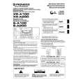
÷ Set the mode selector to FM BAND. ÷ Connect the wiring as shown in Fig. 1. FM SG (1kHz, ±75kHz dev.) Reception Step No. Adjustment Title Frequency (MHz)
1 Front End Sensitivity Stereo Distortion TUNED IND. Lighting Level
Level (dBµV) 0 to 30
Frequency Display 106 MHz
Adjustment Location
L6104 L6105 L6102 T6101 T6101
Specifications
106
Adjust so that the DC voltage between the IC6201Pin 20 and GND becomes at maximum level. Minimize the distortion with 1/8 rotation of the core. Adjust so that the indicator of TUNED IND. starts to light up.
2
98
(ON STEREO)
80 18 ± 2
98 MHz 98 MHz
3
98
VR6201
Note: Before adjusting, make sure there is no gap between L6101 and L6102 as well as between L6103 and L6104. If there is a gap between them, bring them into contact with each other first, and then make adjustments.
7 AM Tuner Section
÷ Set the mode selector to AM BAND. ÷ Connect the wiring as shown in Fig. 1. Step No. Adjustment Title AM SG (400Hz, 30% Mod.) Reception Frequency Adjustment Level Frequency Location Display (kHz) (dBµV/m) 999*1 35 to 45 999kHz*1 T6201 Specifications
1
Front End Sensitivity
Adjust so that the DC voltage between the IC6201Pin 20 and GND becomes at maximum level.
*1: For the area using 10kHz step, frequencies should be 1000 kHz.
60cm Loop antenna
AM SG
Center
Center
AM antenna terminal DC Voltmeter
MPX SG
FM SG FM75� antenna terminal
PRODUCT
Fig. 1
AM and FM Adjustment Wiring Diagram
27
|
|
|
> |
|