|
|
|
Categories
|
|
Information
|
|
Featured Product
|
|
|
 |
|
|
There are currently no product reviews.
 ;
The cover page was a little scary, very dark but readable. The remainder of the document was better copy and easily readable. Why would I give 5 Stars? (1) PRICE, (2) AUTHENTICITY, It was the real deal, filled with service information, including the specific information I required. (3) PRIVACY, I didn't start to get slammed with spam. (4) EASY TRANSACTION. Painless. (5) COMPLETE, I have found several manuals here, that I could find nowhere else. (6) I will be a repeat customer!
;
Well done!!! I found what I need to have, indeed!
Furthermore, due to my hobby is repairing vintage equipments, I added this web site in my desk toolbar because I have in mind to search further service manuals. Thanks a lot www.owner-manuals.com !
Regards, Maurizio
;
Again very good service manual, this time very fast download. AAAAA+
;
Ckear manual, well reproduced with plenty of overlap on critical pages.
;
I buy the service manual cheaper here than in elsewhere.Am happy with this site. I recommended the Owner-Manuals.com
XR-A100, XR-A100-K
5. ADJUSTMENT
Note: Adjustment of MYXK, NVXK and YPWXJ types are the same as those of base model except for the following.
5.1 FM/AM TUNER MODULE (AXQ7077: MYXK and NVXK types only)
7 FM Tuner Section
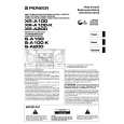
÷ Set the mode selector to FM BAND. ÷ Connect the wiring as shown in Fig. 1. FM SG (1kHz, ±75kHz dev.) Reception Step No. Adjustment Title Frequency (MHz)
1 Front End Sensitivity Stereo Distortion TUNED IND. Lighting Level
Level (dBµV) 0 to 30
Frequency Display 106 MHz
Adjustment Location
L6104 L6105 L6102 T6101 T6101
Specifications
106
Adjust so that the DC voltage between the IC6201Pin 20 and GND becomes at maximum level. Minimize the distortion with 1/8 rotation of the core. Adjust so that the indicator of TUNED IND. starts to light up.
2
98
(ON STEREO)
80 18 ± 2
98 MHz 98 MHz
3
98
VR6201
Note: Before adjusting, make sure there is no gap between L6101 and L6102 as well as between L6103 and L6104. If there is a gap between them, bring them into contact with each other first, and then make adjustments.
7 AM Tuner Section
÷ Set the mode selector to AM BAND. ÷ Connect the wiring as shown in Fig. 1. Step No. Adjustment Title AM SG (400Hz, 30% Mod.) Reception Frequency Adjustment Level Frequency Location Display (kHz) (dBµV/m) 999*1 35 to 45 999kHz*1 T6201 Specifications
1
Front End Sensitivity
Adjust so that the DC voltage between the IC6201Pin 20 and GND becomes at maximum level.
*1: For the area using 10kHz step, frequencies should be 1000 kHz.
60cm Loop antenna
AM SG
Center
Center
AM antenna terminal DC Voltmeter
MPX SG
FM SG FM75� antenna terminal
PRODUCT
Fig. 1
AM and FM Adjustment Wiring Diagram
27
|
|
|
> |
|