|
|
|
Categories
|
|
Information
|
|
Featured Product
|
|
|
 |
|
|
There are currently no product reviews.
 ;
There was no problem at all.After paying i had to wait only a few hours,than i could
download the manual in best pdf-quality.
Thank You !
 ;
I found this service manual to be complete in every detail except for troubleshooting charts. It would be helpful if it had a set of troubleshooting charts; however it is a very good manual otherwise and for the price it is very well worth it.
;
Complete manual included schematics layouts and alignment procedure, clear to read and magnify, extremely pleased with manual and owner manual . com's service
;
perfect, i am very satisfait for the réception of the sansui r-5l service manual, thank you very much
;
Thank you, this is a rare document. Few others have it, but they charge way more for a download.
Great deal (even if you have to wait a few hours to get it).
XR-A330SW, XR-A330EE
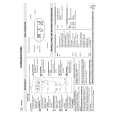
4.2 ADJUSTMENT FOR XR-A330EE
Note : Adjustment of XR-A330EE/MLWXJ/EE are the same as those of XR-A330/DXJ/NC except for the following:
FM Tuner Section
Set the mode selector to FM BAND. Connect the wiring as shown in Fig. 1. FM SG (1kHz, ±75kHz dev.) Step No. Adjustment Title Frequency (MHz) Front End Sensitivity TUNED IND. Lighting Level Level (dBµV) Reception Frequency Display L6104 L6102 T6101 VR6201 Adjust so that the DC voltage between the IC6201-Pin 20 and GND becomes at maximum level. Adjust so that the indicator of TUNED IND. starts to light up. Adjustment Location
Specifications
1
70
0-30
70MHz
2
98
18±2
98MHz
Notes: Before adjusting, make sure there is no gap between L6101 and L6102 as well as between L6103 and L6104. If there is a gap between them, bring them into contact with each other first, and then make adjustments.
AM Tuner Section
Set the mode selector to AM BAND. Connect the wiring as shown in Fig. 1. AM SG (400Hz, 30% Mod.) Step No. Adjustment Title Frequency (kHz) Level (dBµV/m) Reception Frequency Display Adjustment Location Specifications
1
Front End Sensitivity
999*
1
35-45
999kHz*
1
T6201
Adjust so that the DC voltage between the IC6201-Pin 20 and GND becomes at maximum level.
*1: For the area using 10kHz step, frequencies should be 1000kHz
60cm Loop antenna
AM SG
Center
Center
AM antenna terminal
MPX SG
FM SG
PRODUCT
DC voltmeter
FM75� antenna terminal
Fig. 1 AM and FM Adjustment Wiring Diagram
FM/AM TUNER MODULE (AXQ7069)
AM antenna terminal T6201 AXX7041 YELLOW FM antenna terminal BLACK
L6101 T6101 L6102 L6103
VR6201
L6104
Fig. 2 Adjustment Points
14
|
|
|
> |
|