|
|
|
Categories
|
|
Information
|
|
Featured Product
|
|
|
 |
|
|
There are currently no product reviews.
 ;
Excellent concise manual. All needed information was included. Typeface and diagrams were clear. Very fair price considering what others are charging. Many thanks
 ;
Response is a little slow- I had to wait 12 hours to receive download link but it says that it may take up to 24hrs.
Manual is old and was not produced in PDF- scanned copy is exellent.
Overall- value for money- I recommend
;
Excellent quality and quickly delivered manuals at a fair price. Great care is taken in the reproduction process. Even photographs and highly detailed drawings are as clear as in the original. That cannot be said for some freelance manual copies I have obtained from the web. If you have exhausted your internet search of technical manuals, try Owner-Manuals.com. If they do not have it, I do not think it exists. Perhaps, if requested, they may be able to find it. Their resources are certainly greater than most. Shopping here certainly beats waiting for months or years for the manual you seek to appear in an internet auction or garage sale.
;
Very detailed product, also it is a scanning from original, very useful if you have to service this type of amplifier ! Very good product, very hard to find!
;
the Manual was made available as promised, the scans were excellent..Good Work !!!
1
2
3
4
5. ADJUSTMENT
Note : Adjustment of XR-A390 are the same as those of XR-A4800 except for the following:
A
FM Tuner Section
� Set the mode selector to FM BAND. � Connect the wiring as shown in Fig. 1. Step No. Adjustment Title
Front End Sensitivity TUNED IND. Lighting Level
FM SG (1kHz, ± 75kHz dev.) Frequency Level (MHz) (dBµV)
98 98 0 to 30 18 ± 2
Reception Frequency Display
98MHz 98MHz
Adjustment Location
L6402 T6401 VR6201
Specifications
Adjust so that the DC voltage between the IC6201 - pin 20 and GND becomes to maximum level. Adjust so that the indicator of TUNED IND. strats to light up.
1 B 2
Note: Before adjusting, make sure there is no gap between L6401 and L6402. If there is a gap between them, bring them into contact with each other first, and then make adjustments.
AM Tuner Section
� Set the mode selector to AM BAND. � Connect the wiring as shown in Fig. 1.
C
Step No.
Adjustment Title
Front End
AM SG (400Hz, 30% Mod.) Frequency Level (kHz) (dBµV/m)
999 (�1) 35 to 45
Reception Frequency Display
999kHz (�1)
Adjustment Location
Specifications
Adjust so that the DC voltage between the IC6201 - pin 20 and GND becomes to maximum level.
1
Sensitivity
T6201
Note (�1) : For the area using 10kHz step, frequency should be 1000kHz. 60cm Loop antenna
D AM SG Center Center AM antenna terminal
MPX SG
FM SG FM75� antenna terminal
PRODUCT
DC Voltmeter
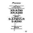
Fig.1 AM and FM Adjustment Wiring Diagram
FM/AM TUNER MODULE
E AM antenna terminal
SIDE A
T6201
YELLOW
BLACK AXX7041 IC6201 Pin 20 VR6201 T6401 L6401
FM antenna terminal
L6402
F
Fig.2 Adjustment Point 20
1 2
XR-A390
3 4
|
|
|
> |
|