|
|
|
Categories
|
|
Information
|
|
Featured Product
|
|
|
 |
|
|
There are currently no product reviews.
 ;
Very usefully, I could find the trouble clearly with that manual.
;
Bon produit. Permet de corriger les couleurs et de redonnez un petit coup de jeune à vos vieilles vidéos. On regrettera juste le manque d'une prise s-vidéo.
 ;
Quality scan of the actual service manual, just what I was looking for.
;
Straightforward ordering process. Service manual scan was clear & easy to read. Very comprehensive instructions for alignment. Excellent, thank you.
;
Fast, clear and useful. Important for me: the manual is in German.
XR-A670, XR-A370
6.2.2 For XR-A370
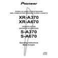
� Adjustment points and test points are shown in Fig.10, Fig.12 and Fig.13.
Mechanical Adjustment
� Test tape : NCT-111 (3kHz, 30min).
1. Tape Speed Adjustment
No. Mode Test Tape Adjusting Points Measurement Points
TAPE TEST POINT (Rch) (AF Assy)
Adjustment Procedure
Press the PLAY SW and adjust so that the reading becomes 3000Hz ± 20Hz. Confirm that wow & flutter level is below 0.3% (in the reverse direction, confirm that the reading is within 3000Hz ± 60Hz).
Remarks
1
Deck � PLAY
ADJ. VR on NCT-111 CASSETTE (Playback : 3kHz) MECHA (Fig. 10)
Tape Speed ADJ. VR AF Assy Front Side Cassette Mechanism Section (Side View)
Fig.10 Tape Speed ADJ. Point
Electrical Adjustment
Check the following before starting.
(1) Confirm that the tape speed adjustment has been completed. (2) Clean the heads and demagnetize them using a head eraser. (3) Set the measurement level to 0 dBV = 1 Vrms. (4) Use the specified tape for adjustment. Use the labeled (A) side of the test tape. STD-331E : For playback check STD-632 : Normal blank tape (5) Provide yourself with the following measuring devides: � AC voltmeter (Noisemeter : filter off) � AC millivoltmeter � Low-frequency oscillator � Attenuator � Oscilloscope (6) Adjust both right and left channels unless otherwise specified. (7) Warm up the unit for several minutes before adjustment. In particular, be sure to warm up the unit in the REC/PLAY mode for 3 to 5 minutes before starting recording/playback frequency characteristics adjustment. (8) Always follow the indicated adjustment order. Otherwise, a complete adjustment may not be achieved.
Playback Adjustment (Decks � and ��)
(1) Head Azimuth Adjustment
Recording Adjustment (Deck �)
(1) Bias Oscillation Frequency Adjustment (2) Recording Bias Adjustment � As the reference recording level is 250nwb/m for STD-331E, the recording level will be higher by 4 dB for STD-331B (160nwb/m). When adjusting, pay carefull attention to the type of tape used.
0 dB 30s 315Hz
0 dB: 315 Hz, 250 nwb/m 30s 6.3kHz 30s 10kHz 30s 315Hz 10s ......................................................................................................... 10s �20 dB 12.5 6.3 500 250 125 14kHz kHz 10kHz 8kHz kHz 4kHz 2kHz 1kHz Hz Hz Hz 63Hz 40Hz 10s
Fig.11 STD-331E Test Tape 63
|
|
|
> |
|