|
|
|
Categories
|
|
Information
|
|
Featured Product
|
|
|
 |
|
|
There are currently no product reviews.
 ;
Excellent concise manual. All needed information was included. Typeface and diagrams were clear. Very fair price considering what others are charging. Many thanks
 ;
Response is a little slow- I had to wait 12 hours to receive download link but it says that it may take up to 24hrs.
Manual is old and was not produced in PDF- scanned copy is exellent.
Overall- value for money- I recommend
;
Excellent quality and quickly delivered manuals at a fair price. Great care is taken in the reproduction process. Even photographs and highly detailed drawings are as clear as in the original. That cannot be said for some freelance manual copies I have obtained from the web. If you have exhausted your internet search of technical manuals, try Owner-Manuals.com. If they do not have it, I do not think it exists. Perhaps, if requested, they may be able to find it. Their resources are certainly greater than most. Shopping here certainly beats waiting for months or years for the manual you seek to appear in an internet auction or garage sale.
;
Very detailed product, also it is a scanning from original, very useful if you have to service this type of amplifier ! Very good product, very hard to find!
;
the Manual was made available as promised, the scans were excellent..Good Work !!!
FM Stereo Separation Adjustment Setting: [SOURCE] button : FM FREQUENCY SELECT switch : FM 200 k
FM RF signal generator antenna jack (J1) 0.01 µF set 10 k� + � level meter
MW Auto Scan/Stop Level Adjustment Setting: [SOURCE]and[MODE]buttons : MW FREQUENCY SELECT switch : MW 10 k
30 � 15 pF
65 pF
AM RF signal generator AM dummy antenna (50 �) Carrier frequency : 1000 kHz 30% amplitude modulation by 1 kHz signal Output level : 33 dB (44.7 µV)
Carrier frequency Output level Mode Modulation
AUDIO OUT REAR jack : 97.9 MHz (CNJ151) : 70 dB (3.2 mV) : stereo : main: 1 kHz, 33.75 kHz deviation (45%) sub: 1 kHz, 33.75 kHz deviation (45%) 19 kHz pilot: 7.5 kHz deviation (10%)
set
antenna jack (J1)
Procedure:
FM Stereo signal generator output channel L-CH R-CH R-CH L-CH L-CH L-CH R-CH R-CH A B Adjust RV4 on TU1 for minimum reading. C D Adjust RV4 on TU1 for minimum reading. Level meter connection Level meter reading (dB)
Procedure: 1. Set to the test mode. (See page 13) 2. Push the[SOURCE]button and set to FM. 3. Push the[MODE]button and set to MW. Display
L-CH Stereo separation: A-B R-CH Stereo separation: C-D The separations of both channels should be equal. Specification: Separation more than 30 dB Adjustment Location: See page 16.
TP
SHUF
4. Adjust with the volume RV1 on TU1 so that the �MW� indication turns to �MW0� indication on the display window. But, in case of already indicated �MW0�, turn the RV1 so that put out light �0� indication and adjustment. Display
TP
SHUF
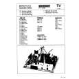
Adjustment Location: See page 16.
� 15 �
|
|
|
> |
|