|
|
|
Categories
|
|
Information
|
|
Featured Product
|
|
|
 |
|
|
There are currently no product reviews.
 ;
Good-quality scans. Detailed description. I hope I can repair the machine.
;
High-quality scanning. Detailed description. Recommend for all technician. A+++
;
This is a good quality scan of the original Service Manual from Nordmende, Germany. Contains the circuit diagram, PCB layout, adjust/tune instructions as well. It is NOT in English but in GERMAN language! That was quite right for my german friend from the lower east side in Berlin.
 ;
Received via e-mail this PDF manual is worth the money. This is a quality scan of a manual in excellent condition and is just as good as having the original manual in hand. I have later seen the original manual and it was printed in colour, but this particular manual is black & white but scan resolution is high end quality! All drawings and pictures are presented in great detail. So, nearly perfect score in my opinion.
If you own the turntable you also should own the manual!
;
I was very satisfied with the service manual I ordered and downloaded. I will definitely buy again from this seller.
XR-CA624X
4A
B
c
51
182 m m
2
3
4 5 4
4
Dashboard �表� #####
Fire wall
1
��� #####
6 2 3
53 mm
Bend these claws outward for a tight fit, if necessary.
1
�������������� #####
5 5 4
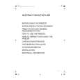
Precautions
�Choose the installation location carefully so that the unit will not interfere with normal driving operations. �Avoid installing the unit in areas subject to dust, dirt, excessive vibration, or high temperatures, such as in direct sunlight or near heater ducts. �Use only the supplied mounting hardware for a safe and secure installation. �There must be a distance of at least 15 cm between
the cassette slot of the unit and shift lever in order to insert a cassette easily. Choose the installation location carefully so the unit does not interfere with gear shifting and other driving operations.
Mounting example (5)
Installation in the dashboard
使ç�¨å��注æ��äº�é �
â�¢ ä»�ç´°é�¸æ��å®�è£�ä½�ç½®ï¼�使ä¹�ä¸�妨ç¤�æ£å¸¸ç��é§�é§�æ��ä½�ã�� â�¢ é�¿å��å°�æ�¬æ©�æ�¾å�¨é«�溫ä¹�è��ï¼�å¦�é�½å��ç�´æ�¥ç�§å°�ã��æ�� æ°£æ©�å��ã��æ��ç�°å¡µæ¥µå¤�ã��é«�äº�ï¼�以å��極æ��å��é��å��ç� å�°æ�¹ã�� â�¢ ç�ºä½¿å®�è£�å¾�以å®�å�¨å��å�¯é� ï¼�ç¥�è�½ä½¿ç�¨æ��ä¾�ç��å®�è£� é�¶ä»¶ã�� â�¢å�¨æ�¬æ©�ç��å�¡å¸¶æ§½å�£å��è®�é��æ¡¿ä¹�é��ï¼�è�³å°�é��ä¿�æ�� 15 cm è·�é�¢ä»¥ä¾¿æ�¼è£�æ��å�¡å¸¶ã��è«�ç��å¿�é�¸æ��å®�è£�ä½� 置以便使æ©�å�¨ä¸�è�³æ�¼å¦¨ç¤�æ�¨æ��æª�å��å�¶ä»�é§�è»�æ�� ä½�ã��
��示��5�
������裡
Mounting the unit in a Japanese car (6)
You may not be able to install this unit in some makes of Japanese cars. In such a case, consult your Sony dealer.
Note To prevent malfunction, install only with the supplied screws 4.
���������汽��� 6 ��
�����汽����������種�形��� ����� Sony ���諮詢�
註 ç�ºé�²æ¢ç�¼ç��æ��é��ï¼�å®�è£�æ��å�ªè�½ä½¿ç�¨é��é��ç��è�ºçµ² 4ã��
15 cm 15 cm
Warning when installing in a car without ACC (accessory) position on the ignition key switch
Be sure to press (OFF) on the unit for two seconds to turn off the clock display after turning off the engine. ���度�調�
�� 20 °以�調����度�
å®�è£�å�¨é»�ç�«é�°å��é��é��ä¸�æ²�æ�� ACC ï¼�è¼�å�©ï¼�ä½�ç½®ç��æ±½è»�ä¸�æ��ç��è¦å��
���汽��������������� (OFF) ��以����顯示�
å¦�æ��å�ªç�æ�«å�°æ��ä¸�ä¸� (OFF)ï¼�å°�ä¸�æ��é��æ��æ��é��顯 示è��浪費é�»æ± ã��
Mounting angle adjustment
Adjust the mounting angle to less than 20°.
When you press (OFF) only momentarily, the clock display does not turn off and this causes battery wear.
RESET �� 4 ����������� �
ç�¶å®�è£�å��é�£æ�¥å®�æ��å¾�ï¼�å��è«�ç�¨å��ç� ç�ç�æ��å£� RESET æ��é��ã��
How to detach and attach the front panel (4)
Before installing the unit, detach the front panel.
���������������
RESET button
When the installation and connections are completed, be sure to press the RESET button with a ballpoint pen, etc.
4-A ��
æ��å�¸å��é�¢æ�¿ä¹�å��ï¼�é �å��æ��ä¸� (OFF) é�µã��ç�¶å¾�ï¼�æ�� (OPEN) ä¸� é�µä»¥ä¾¿é��å��å��é�¢æ�¿ï¼�å°�å��é�¢æ�¿ç¨�å¾®å�� å�³é��æ»�å��ï¼�ç�¶å¾�å°�å��é�¢æ�¿ç��å·¦å�´æ��å�ºã��
4-A To detach
Before detaching the front panel, be sure to press (OFF). Press (OPEN), then slide the front panel to the right side, and pull out the left side.
4
-B
��
å�æ�å�¨æ�¬æ©�ç��æ�¯è»¸
���示������ ������左��
4-B
To attach
Place the hole in the front panel onto the spindle on the unit as illustrated, then push the left side in.
7
|
|
|
> |
|