|
|
|
Categories
|
|
Information
|
|
Featured Product
|
|
|
 |
|
|
There are currently no product reviews.
 ;
It's the manual, I am searching for. Now I am able to repair my Braun A501.
 ;
Great service manual. Unfortunately on page no. 41 there are some details which i can't read.
;
Wonderful service... doubt that I could have made the repairs to my turntable without this service manual. Great help!
Well worth the price paid!
;
nice completed SERVICE MANUAL as the description THANK YOU !!!-
;
The service manual is as described and received the link to the download sooner than expected. Great service, quality product. This site is a big help in the electronics repair business.
<CD SECTION>
PWB CD
6
VC R546
1
RIOP
SFR501 FE TE
4
IC501
RF
2 3
IC651
CD Adjustment Method �Perform the adjustments after the machine enters the test mode. �Place the CD mechanism on level ground. �Equipment and tools required Measuring equipment: Oscilloscope (Use the probe of 10:1) Digital Multimeter (Use it in the DC Volt range) Jitter meter (Kikusui 6235) Test Disc: TCD-782 ATD-001 1. Focus Offset Adjustment 1) Connect a digital multimeter to the test point (FE), (VC). 2) Play back the 2nd track of TCD-782. 3) Adjust SFR501 until the digital multimeter indicates 0 ± 10 mV. 2. RF Waveform Check 1) Connect an oscilloscope to test point (RF), (VC). 2) Play back the 2nd track of TCD-782. 3) Check that the RF waveform has the maximum amplitude and the center of the wedge waveform has the clear blank.
RF OSCILLOSCOPE
Approx.
DIGITAL MULTIMETER V FE VC
OUTPUT
1.8 ± 0.3 Vp-p EYE PATTERN must be CLEAR and MAX 0V VOLT / DIV: 500mV
3. Jitter Check 1) While an oscilloscope is kept connected in the same test point as in step 2. RF Waveform Check, connect the output terminal of an oscilloscope to the input terminal of the jitter meter. 2) Set the VOLT range selector of an oscilloscope to 500 mV range or lower. 3) Play back the 2nd track of TCD-782. 4) Check that the jitter meter indicates 28.0 ns or less.
VC
OSCILLOSCOPE JITTER METER OUTPUT INPUT ns
RF VC
� 38 �
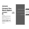 $4.99 XREM70 AIWA
Owner's Manual Complete owner's manual in digital format. The manual will be available for download as PDF file aft…
|
|
|
> |
|