|
|
|
Categories
|
|
Information
|
|
Featured Product
|
|
|
 |
|
|
There are currently no product reviews.
 ;
Once again owner-manual.com has saved the day for me, and come through with the manual I need. I looked other places too, and couldn't find it anywhere. Thank You owner-manual.com!!! You're the BEST!
;
very good quality that can be magnified several times, and it remains readable.
For sure I will return next time the need for a service manual arise.
;
The service manual is really great - thanks to it I was able to install the laser unit and thus "save" my CD-player, which seemed to be impossible before I had the manual.
;
Downloaded the Service manual OK of the Technics Piano and have now repaired it and its going fine. Excellant; thank you for the fine servce. A.M
 ;
This site is working fine! Did buy a manual for SX-EX25L and after a while I could download it and fix the problem. Nice and easy!
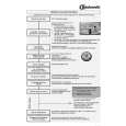
ELECTRICAL ADJUSTMENT-13/13
3. JITTER CHECK
1) While oscilloscope is kept connected in the same test point as in step2. RF WAVEFORM CHECK, connect the output terminal of an oscilloscope to the input terminal of the jitter meter. 2) Set the VOLT range selector of oscilloscope to 500mV range or below. 3) Play back 2nd track of TCD-782. 4) Check that jitter meter indicates 28.0ns or less.
OSCILLOSCOPE JITTER METER OUTPUT INPUT ns
RF SW Vref
4. PLAY ABILITY CHECK
1) Play back the 3rd , 8th and 13th track of ATD-001. Check that the noise does not occur sound skipping does not occur.
5. LASER CURRENT CHECK
* Do not perform this measurement unless the laser is suspected to be defective. 1) Connect digital multi-meter across the resistor R402(10�). 2) Play back the TCD-782 and check the DC voltage value on the digital multimeter. 3) Calculate the laser current (Iop) by dividing the DC voltage across R402 by the resistor value (R402= 10�). Check that the laser current (Iop) is 60mA or less.
DIGITAL MULTIMETER V
R402 R402
-35-
|
|
|
> |
|