|
|
|
Categories
|
|
Information
|
|
Featured Product
|
|
|
 |
|
|
There are currently no product reviews.
 ;
Great item, high resolution, detailed, very easy to work with.
;
fast delevery of the manual and very complete manual, now my Akai works again, will buy again, thanks.
 ;
Tartalma megfelelő. Szebb kivitelű is lehetne a scannelés.
;
I never been disappointed in my dealings with owners-manuals.com
;
Excellent printing quality. A complete and very useful manual with all details.
CD Adjustment Method
� Perform the adjustments after the machine enters the test mode. � Place the CD mechanism horizontally level. � Equipment and tools required Measuring equipment: Oscilloscope (Use the probe of 10:1) Digital VOM (Use it in the DC Volt range.) Jitter meter (Kikusui 6235 or equivalent) Test disc: TCD-782 ATD-001
1. FOCUS BIAS Adjustment
1) 2) 3) Connect a digital VOM to the test point (FOCUS BIAS), (VREF). Play back the 2nd track of the TCD-782. Adjust SFR430 until the VOM indicates 0 +/-10 mV.
DIGITAL MULTIMETER V
+
FOCUS BIAS VREF
--
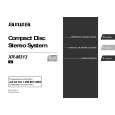
2. RF Waveform Check
OSCILLOSCOPE
1) 2) 3)
Connect an oscilloscope to test point (RF SM), (GND). Play back the 2nd track of the TCD-782. Check to see that the RF waveform has the maximum amplitude and the center of the wedge waveform has the clear blank.
RF SM VREF
1.8 Vp-p
OUTPUT
+
--
EYE PATTERN must be CLEAR and MAX.
0V
VOLT/DIV: 500mV TIME/DIV: 0.5µS
3. Jitter Check
1) While an oscilloscope is kept connected in the same test point as in the 2. RF Waveform Check, connect the output terminal of an oscilloscope to the input terminal of a jitter meter. Set the VOLT range selector of an oscilloscope to 500 mV range or lower. 3) 4) Play back the 2nd track of the TCD-782. Check to see that a jitter meter indicates 28.0 ns or less.
RF SM VREF OSCILLOSCOPE JITTER METER OUTPUT INPUT ns
2)
+
--
4. Tracking Balance Check
1) 2) 3) Connect an oscilloscope to test point (TE), (VREF). Play back the 2nd track of the TCD-782 and press the PAUSE button. Check to see that the traverse waveform on an oscilloscope is vertically symmetrical.
TE VREF OSCILLOSCOPE
VREF
OUTPUT
A B
+
--
A=B
VOLT/DIV: 500mV TIME/DIV: 1mS
5. Play-ability Check
1) Play back the 3rd, 8th and 13th track of ATD-001. Check to see that noise does not occur and sound skipping does not occur.
6. Laser Current Check
*Do not perform this measurement unless the laser is suspected to be defective. 1) Connect a digital VOM across the resistor R402 (10 ohms). 2) Play back the TCD-782 and check the DC voltage value on a digital VOM. 3) Calculate the laser current (Iop) by dividing the DC voltage across R402 by the resistor value (R402 = 10 ohms). Laser current (Iop) = DC voltage across R402 divided by the resistor value (10 ohms). Check to see that the laser current (Iop) is 80 mA or less.
DIGITAL MULTIMETER V
+
R402 R402
--
� 31 �
 $4.99 XRM313 AIWA
Owner's Manual Complete owner's manual in digital format. The manual will be available for download as PDF file aft…
|
|
|
> |
|