|
|
|
Categories
|
|
Information
|
|
Featured Product
|
|
|
 |
|
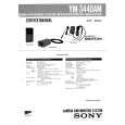
- GENERAL
- Location and Function of Controls
- Monitor Adjustment and Preparation
- Color Adjustment and Correction During Editing
- DISASSEMBLY
- Removal of Cabinet, Front Panel
- Removal of FT - 38 Board
- Removal of FT - 39 Board
- Opening of CA - 16 Board
- Opening of WF - 1 Board
- DIAGRAMS
- Circuit Boards Location
- Color Correct Block Diagram
- Back Color Signal Generator Block Diagram
- Audio/Power Block Diagram
- PRINTED WIRING BOARDS AND SCHEMATIC DIAGRAMS
- Frame Schematic Diagram
- Printed Wiring Boards and Schematic Diagrams
- FT - 39, FT - 38, JK - 44, AM - 13, IS - 5 and MJ - 22 Boards
- AC - 44, PT - 68, PT - 70 and PW - 61 Boards
- Semiconductors
- EXPLODED VIEWS
- Cabinet, Front Panel Assemblies
- Main Board Assembly
- ELECTRICAL PARTS LIST
- ELECTRICAL ADJUSTMENT
- Adjustment of Power Supply Block
- - 5V, +9V Adjustment
- +5V, +6V and - 6V Confirmation
- Adjustment of Internal SYNC. Signal and Timing Generator
- INT SYNC fsc Adjustment
- INT SYNC Burst Level Confirmation
- INT SYNC Level Confirmation
- H AFC Adjustment
- H Front Blanking Adjustment
- H Back Blanking Adjustment
- V Blanking Adjustment
- Adjustment of Composite Video Signal System
- Y - SEP Level Adjustment
- C - SEP Frequency Characteristic Adjustment
- C - SEP Level Adjustment
- Y - C SEP Frequency Characteristic Adjustment
- Composite Y Level and Chroma Level Adjustment
- Adjustment of Y Main Signal System, Negative/Positive Inverter and Y - γ Circuit
- Pilot Signal Level Adjustment
- Negative AGC Adjustment
- Y - γ Center Adjustment
- Positive AGC Adjustment
- Y - γ LOW and Y - γ HIGH Adjustment
- C - γ Adjustment
- Y Level and SYNC Level Adjustment
- Adjustment of Chroma Main Signal System and Burst Signal System
- COLOR VR Center Adjustment
- Chroma Lever Adjustment
- Burst Phase Adjustment (Using the Vectorscope)
- Burst Level Adjustment
- CNR Adjustment
- Adjustment of Fader/Wipe Back Color System
- Back Color Bar Adjustment
- Fader/Wipe Back Color Y Level and Back Color Y Level Adjustment
- Fader White Level Adjustment
- fsc Adjustment
- ACC Peak Adjustment
- ACC Adjustment
- Fader/Wipe Back Color Chroma Level/Phase Adjustment (Using the Vectorscope)
- Fader/Wipe Back Color Chroma Level/Phase Adjustment (Using the Oscilloscope)
- Back Color INT Mode Phase Adjustment
- Adjustment of Color Correct System
- Color Correct Carrier Balance Adjustment
- Chroma Limiter Adjustment
- Color Correct Phase Adjustment (Using the Vectorscope)
- Color Correct Position Adjustment (Using the Monitor TV)
- Color Correct Level Adjustment
- Adjustment of Wipe System
- H RAMP Level Adjustment
- V RAMP Level Adjustment
- H RAMP, V RAMP DC Clamp Level Adjustment
- Diamond Pattern Center Adjustment
- Round Wipe Pattern Roundness Adjustment
- Round Wipe Pattern Position Adjustment
- Round Wipe Pattern Size Adjustment
- Adjustment of VIDEO ART and Split Screen System
- VIDEO ART REVERSE Level Adjustment
- VIDEO ART VR Center Adjustment
- Split Screen Adjustment
- Adjustment of Audio System
- Audio Output Level Adjustment
- Parts Location Diagram Relevant to the Adjustment
There are currently no product reviews.
 ;
The manual describes this product very good. It has the basic things to know and also a more detailed look. Very well made!
;
An excellent document to assist in the repair of my old personal tape player. It includes full circuit diagrams and physical layout drawings and full instructions on disassembly and fault finding.
Well worth the meagre price.
;
Very good conversation, Pretty fast Service, wood do it again,
Have paid by Paypal, so i got the Service Manual online after 15 Min.
Very helpfully.
Greeting from Germany,
Hans
;
Good-quality scans. Detailed description. I hope I can repair the machine.
;
High-quality scanning. Detailed description. Recommend for all technician. A+++
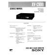 $4.99 XV-C900 SONY
Owner's Manual Complete owner's manual in digital format. The manual will be available for download as PDF file aft…
|
|
|
> |
|