|
There are currently no product reviews.
 ;
Good Quality of the File.
You get the normal manual is incudet.
;
Very nice and real Service Manual, I didn't thought it actually exist in the real world at all.
 ;
VERY NICE FOR COURTESY AND PRECISION!.
tHE SITE IS VERY IMPORTANT FOR ALL DEVICES
vERY GOOD
;
+++ Is is fine, that was what i looking for. Thanks! +++
;
A very good complete archive, i am very satisfied for document.
1
2
3
4
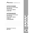
2 Bridge 04, Tray
A
1 2 3
Remove the one screw. Remove the bridge 04. Pull out the tray, then remove it by pressing the hook.
3
-2
Hook
B
Bridge 04
1 2
C
3
-1
Tray
D
E
Note when reinserting the tray
When reinserting the tray, first align the triangle printed on the loading base and the pin of the drive cam, then insert the tray. Drive cam Pin
Front side
F
Loading base
Triangle
82
1 2
XV-DV360
3 4
|