|
|
|
Categories
|
|
Information
|
|
Featured Product
|
|
|
 |
|
|
There are currently no product reviews.
 ;
This manual was very clear and complete, the prices can't be beat, great to have older manuals available!
 ;
Doubted for buy this manual as it is my first order here and at not have cover image, I assumed would haven't. However, within 24 hs, already possessed the link to download it. The manual are scanned correctly and have all what is needed. Includes adjustments and diagrams of all circuits. Very satisfied.
;
Really good quality, аll readable.! Wonderful work shop. I recommend to all!
;
Good quality service manual.The scheme is on A3 format and very readable.Thank you
;
Very good service-manual with clear electrical diagrams. Thanks you.
1
2
3
4
A
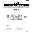
Protection circuit that activates against a PRTCT ERR error
2 When the main power supply becomes LO level because of short-circuit or disconnection of connectors
2 -1 Short-circuit-detection circuit for the amplifier power circuit (VH+[VP+15], VD+5, -12 V [VA-12]) Circuit for shutting the power off when VP+15, VD+5, or VA-12 is short-circuited to ground (GND)
VH+ (VP+15) Q101_2/2 D101 (D102)
B E2 (Q103_2/2) B2 C2 C2 E2
2 -3 Short-circuit-detection circuit for VFDP
D
6CH AMP Assy
VD+5 R108 27k
H
TRADE2 Assy
D
B
6CH AMP Assy
VD+5
VD+5
(Q103_1/2) R108 27k to XPROTECT C (µ-com) Q102_1/2 (Q104_1/2)
E
Q101_1/2 E
C B
Q102_2/2 (Q104_2/2)
B2
to XPROTECT (µ-com) Q115 DTA124EUA Q114 2SD2114K (VW) VA-12
B
R102 (R105) 10k
R112 1k
R114 82k
FL AC2
R101 (R104) 1k + C101 (C102) 1/50
R113 220k
A
R103 (R106) 10k
R109 820 D105 (D106) VH� (VA�12)
* ( )means the wiring No. of VP+15 line.
If VFDP is short-circuited to GND, or if the DC electric potential at FL AC1 becomes GND level (in Normal mode: about -27 V) because of a failure in the DC bias circuit of FL AC1, Q114 then Q115 are turned on, and the level of XPROTECT becomes low. � The microcomputer detects the XPROTECT level and shuts the power to the unit off.
� In Normal mode, as Q101 (Q103) (E2, B2, C2) and Q102 (Q104) (E2, B2, C2) are on, the voltage at Point A is about 5 V. The voltage at Point B is therefore about the same. As Q101 (Q103) (E, C, B) is off, Q102 (Q104) (E, C, B) is also off.
C
(1) When VH+(VP+15) is short-circuited to GND As the voltage at Point B becomes almost ground potential, and Q101 (Q103) (E, C, B) then Q102 (Q104) (E, C, B) are turned on, the level of XPROTECT becomes low. � The microcomputer detects the XPROTECT level and shuts the power to the unit off. (2) When VH-(VA-12) is short-circuited As the electric potential of VE at Q102 (Q104) (E2, C2, B2) becomes the same as that at VB, Q102 (Q104) (E2, C2, B2) is turned off. Following this, Q101 (Q103) (E2, B2, C2) is turned off, which changes the voltage at Points A and B to a value other than 5 V. Therefore, Q101 (Q103) (E, C, B) then Q102 (Q104) (E, C, B) are turned on, the level of XPROTECT becomes low. (3) When VD+5 is short-circuited The level of the XPROTECT line becomes low. The microcomputer detects the XPROTECT level and shuts the power to the unit off. 2 -2 Short-circuit-detection circuit for the DVD power supply (VP+8)
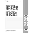
3 When the FAN connector is disconnected or when rotation of the fan is interrupted
D
6CH AMP Assy
VD+5 VPF+15 R3654 1.8k
C B2 E
D
to XPROTECT (µ-com)
R108 27k
C2
D3658 UDZS7.5B
B
A
Q3651_2/2 RN1901
Q3652 DTA124TK R3657 33(1/4W) FAN+ D3655 1SS133 FAN� D3651-D3654 1SS133�4 R3656 22k V-12F
E2
+
R3658 2.2k
Q3651_1/2 C3652 D3657 RN1901 47/50 1SS355 R3655 8.2k Q3654 2SD2144S
D
E
6CH AMP Assy
VD+5 R108 27k
VP+8 D104 1SS355
XPROTECT
If no fan is connected between FAN+ and FAN-, or when the fan cannot rotate because of a foreign object caught in the blades, the BASE of Q3652 becomes OPEN, and Q3652 and Q3651-1/2 (E, C, B) are turned off. Then Q3651-2/2 (E2, B2, C2) is turned on, and the level of XPROTECT becomes low. � The microcomputer detects the XPROTECT level and shuts the power to the unit off. When FAN+ and FAN- are short-circuited, the electric potential at Point A becomes higher than GND level by the addition of the values at D3656 and D3657. As this value is lower than that at D3658, Q3651 (E, C, B) is turned off, Q3651 (E2, B2, C2) is turned on, and the level of XPROTECT becomes low.
Q106 DTC124EUA Q107 DTA124EUA TUNER
F
As the TUNER line is fixed to GND level, Q107 is always on. If the level at VP+8 falls to GND level because of short-circuit, etc., Q106 is turned on, and the level of the XPROTECT line becomes low. � The microcomputer detects the XPROTECT level and shuts the power to the unit off.
116
1 2
XV-DV525
3 4
|
|
|
> |
|