|
There are currently no product reviews.
 ;
Very clear copy. No pages missing. Big bonus is that it includes supplement. Price is affordable compared to what others ask for.
;
Found the quality of the copy excellent and a very quick service. I would certainly recommend the service.
;
Good quality, clear diagrams. Exactly what I needed.
 ;
Good product. All the information is invcluded, but due to the complexity of the amplifier, it still is difficult to get it to operation again.
;
Very professional seller; very fast, accurate and rielable service.
5
6
7
8
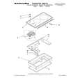
7. DISASSEMBLY
Note 1: Do NOT look directly into the pickup lens. The laser beam may cause eye injury. Note 2: Even if the unit shown in the photos and illustrations in this manual may differ from your product, the procedures described here are common.
A
Diagnosis of PCB's
1 Bonnet, Tray Panel
1 2 3 4 5 6 7 8
Remove the bonnet by removing the nine screws. Press the � STANDBY/ON button to turn on the power. Press the � OPEN/CLOSE button to open the tray. Remove the tray panel. Set the test disc. Press the � OPEN/CLOSE button to close the tray. (Test disc is clamped.) Press the � STANDBY/ON button to turn off the power. Pull out the Power cord. Test disc
27
B
5 4
3
6
Tray panel
Tray
36
C
D
How to open the tray when the power cannot be on
Insert a screwdriver (small) into the slit located at the bottom of the unit, and slide the projection of the drive cam in the 06 LOADER Assy in the direction of the arrow, as indicated in the photo. If the tray pops out a little, fully pull it out by hand.
Projection
Screwdriver (small)
E
Slit Tray open
Drive cam 06 LOADER Assy Bottom view Screwdriver (small)
F
XV-DV363
5 6 7 8
33
|