|
|
|
Categories
|
|
Information
|
|
Featured Product
|
|
|
 |
|
|
There are currently no product reviews.
 ;
Response is a little slow- I had to wait 12 hours to receive download link but it says that it may take up to 24hrs.
Manual is old and was not produced in PDF- scanned copy is exellent.
Overall- value for money- I recommend
 ;
Excellent quality and quickly delivered manuals at a fair price. Great care is taken in the reproduction process. Even photographs and highly detailed drawings are as clear as in the original. That cannot be said for some freelance manual copies I have obtained from the web. If you have exhausted your internet search of technical manuals, try Owner-Manuals.com. If they do not have it, I do not think it exists. Perhaps, if requested, they may be able to find it. Their resources are certainly greater than most. Shopping here certainly beats waiting for months or years for the manual you seek to appear in an internet auction or garage sale.
;
Very detailed product, also it is a scanning from original, very useful if you have to service this type of amplifier ! Very good product, very hard to find!
;
the Manual was made available as promised, the scans were excellent..Good Work !!!
;
It's complete and helpful manual with good quality of scan. Thanks very much.
5
6
7
8
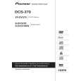
7. DISASSEMBLY
Note 1: Do NOT look directly into the pickup lens. The laser beam may cause eye injury. Note 2: Even if the unit shown in the photos and illustrations in this manual may differ from your product, the procedures described here are common.
A
Diagnosis of PCB's
1 Bonnet, Tray Panel
1 2 3 4 5 6 7 8
Remove the bonnet by removing the nine screws. Press the � STANDBY/ON button to turn on the power. Press the � OPEN/CLOSE button to open the tray. Remove the tray panel. Set the test disc. Press the � OPEN/CLOSE button to close the tray. (Test disc is clamped.) Press the � STANDBY/ON button to turn off the power. Pull out the Power cord. Test disc
27
B
5 4
3
6
Tray panel
Tray
36
C
D
How to open the tray when the power cannot be on
Insert a screwdriver (small) into the slit located at the bottom of the unit, and slide the projection of the drive cam in the 06 LOADER Assy in the direction of the arrow, as indicated in the photo. If the tray pops out a little, fully pull it out by hand.
Projection
Screwdriver (small)
E
Slit Tray open
Drive cam 06 LOADER Assy Bottom view Screwdriver (small)
F
XV-DV363
5 6 7 8
33
|
|
|
> |
|