|
There are currently no product reviews.
 ;
Very nice and real Service Manual, I didn't thought it actually exist in the real world at all.
 ;
VERY NICE FOR COURTESY AND PRECISION!.
tHE SITE IS VERY IMPORTANT FOR ALL DEVICES
vERY GOOD
;
+++ Is is fine, that was what i looking for. Thanks! +++
;
A very good complete archive, i am very satisfied for document.
;
The Service Manual received was helpful. The electronic information is exactly what I needed.
5
6
7
8
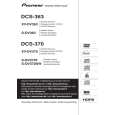
7. DISASSEMBLY
Note 1: Do NOT look directly into the pickup lens. The laser beam may cause eye injury. Note 2: Even if the unit shown in the photos and illustrations in this manual may differ from your product, the procedures described here are common.
A
Diagnosis of PCB's
1 Bonnet, Tray Panel
1 2 3 4 5 6 7 8
Remove the bonnet by removing the nine screws. Press the � STANDBY/ON button to turn on the power. Press the � OPEN/CLOSE button to open the tray. Remove the tray panel. Set the test disc. Press the � OPEN/CLOSE button to close the tray. (Test disc is clamped.) Press the � STANDBY/ON button to turn off the power. Pull out the Power cord. Test disc
27
B
5 4
3
6
Tray panel
Tray
36
C
D
How to open the tray when the power cannot be on
Insert a screwdriver (small) into the slit located at the bottom of the unit, and slide the projection of the drive cam in the 06 LOADER Assy in the direction of the arrow, as indicated in the photo. If the tray pops out a little, fully pull it out by hand.
Projection
Screwdriver (small)
E
Slit Tray open
Drive cam 06 LOADER Assy Bottom view Screwdriver (small)
F
XV-DV363
5 6 7 8
33
|