|
|
|
Categories
|
|
Information
|
|
Featured Product
|
|
|
 |
|
|
There are currently no product reviews.
 ;
This manual is complete and of high quality. I am very pleased with the purchase.
;
Another excellent buy! A fully readable PDF archive. Good prints!!
;
It is wonderful done!!! a great job in scanning the manual. Superior quality in all the electric scheme. Very understandable and net!!! Thank you!
 ;
muy buen manual por lo completo de este algunos esquemas estan muy divididos lo que hace algo dificil el seguimiento.
;
very good manual, with detail and clarity in esquematic diagrams and waveforms .
1
2
3
4
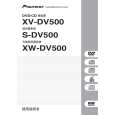
4 When DC is generated at the output because of a failure in the AMP system, etc.
5 When abnormally high temperature is detected by the thermistor
5 -1 IC81 abnormal temperature detection circuit
VD+5 IC81 NJM7805FA TH111 NCP18WF104J03RB
A
J
R3605 (R3625) (R3615) 27k Q3637 R3606 (R3626) (R3616) 27k + R3638 10k C3632 470/6.3
POWER Assy
D
VD+5
6CH AMP Assy
D
+5V Q3632
E B C
6CH AMP Assy
to XPROTECT
R108 27k
Front L ch (SW, SL) Front R ch (C, SR)
A
XPROTECT R111 1k
R113 220 R112 1k
Q111 2SC4081
Q3638
Q3633
The voltage at Point A becomes the divided voltage of TH111 and R111//R112 (combined resistance of parallel-connected � In Normal mode, both Q3637 and Q3638 are off. (1) When positive (+) DC voltage is generated at the SP terminal When positive (+) DC voltage is generated at the L or R channel, and VB of Q3637 becomes higher than that at the operation point, Q3632 (E, C, B) is turned on, and the level of XPROTECT becomes low. � The microcomputer detects the XPROTECT level and shuts the power to the unit off. (2) When negative (-) DC voltage was generated at the SP terminal Q3638 is turned on, and XPROTECT is activated. resistors R111 and R112.) In Normal mode, the resistance at TH111 is much higher than R111//R112, and Q111 is off. (Note that the resistance at TH111 becomes lower as the temperature increases.) If the solder temperature at IC81 increases abnormally, the temperature at TH111 (thermistor) mounted closest to the land of IC81 increases accordingly, and the resistance at TH111 decreases. When the temperature at TH111 reaches 90-110_C (varying according to conditions,) the voltage at Point (A) becomes high enough to turn Q111 on, and the level of the XPROTECT line becomes low. The microcomputer detects the XPROTECT level and shuts the power to the unit off.
B
C
D
E
F
XV-DV430
1 2 3 4
111
|
|
|
> |
|