|
|
|
Categories
|
|
Information
|
|
Featured Product
|
|
|
 |
|
|
There are currently no product reviews.
 ;
This is a great site. I placed my order and by the next am it was available for download. Had some problems with some missing copy on some pages. Once I brought the error to the OMC's attention, the issue was resolved. I'll come back again.
 ;
Mi spiace per non poter scrivere in inglese... ma sono veramente soddisfatto del servizio offerto. Grazie..!!
;
The quality of this manual is good. It has all schematics and setup information for both the MDS-B3 and the MDS-B4. The scan quality is quite good, all pages are readable, This service manual also contains scans of the operating instructions from the User manual.
;
Quick site processing. A complete and very useful manual with all details. Thank you!
;
Das Service Manual war von der ersten bis zur letzten Seite sehr informativ und hilfreich. Die Darstellung aller Teile war klar und der Text gut lesbar.
Vielen Dank, das war nicht der letzte Download bei ownner-manuals.com.
5
6
7
8
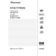
7. DISASSEMBLY
Note 1: Do NOT look directly into the pickup lens. The laser beam may cause eye injury. Note 2: Even if the unit shown in the photos and illustrations in this manual may differ from your product, the procedures described here are common.
A
Disassembly
1 Bonnet, Tray Panel
1 1 2 3 4 5 6 7
Remove the bonnet by removing the nine screws. Press the u STANDBY/ON button to turn on the power. Press the h OPEN/CLOSE button to open the tray. Remove the tray panel. Set the test disc. Press the h OPEN/CLOSE button to close the tray. (Test disc is clamped.) Press the u STANDBY/ON button to turn off the power. Pull out the Power cord. Test disc
B
4
3 2 5
Tray panel Tray
25 16
C
D
How to open the tray when the power cannot be on
1. Slide the rack, loading (White) toward the arrow direction by using a minus screwdriver to release the lock. 2. Manually open the tray. NOTE: Please strongly pushing rack, loading (White) to release the lock because the tray doesn't go out easily.
Minus screwdriver
E
Rack, loading (White) Tray open
F
Bottom view
XV-DV575
5 6 7 8
33
|
|
|
> |
|