|
|
|
Categories
|
|
Information
|
|
Featured Product
|
|
|
 |
|
|
There are currently no product reviews.
 ;
Excelent service, the manual is complete, very cheap and fast
Alberto
;
The item received was as described, as expected. I was pleased with the order. Thank you.
 ;
Superb rendition. Drawings (schematics) complete and unabridged. I do a great deal of vintage audio restoration. Documentation is essential for successful repairs. I have found sources over the years that offer good documentation, but rarely all that is necessary. Owner's Manuals has filled that void with complete and legible documentation. They have narrowed my "favorites" to a more manageable collection. This Denon manual in particular contained the latest revisions level, and offered alterations favorable to updating the item. The Illustrated Parts Breakdown (IPB) was well enough detailed to simplify part symbols and physical locations. You will not be disappointed!
;
Clear and concise. Saved me a lot of time and money.
;
Superb manual. Exactly what I ordered and made available in a very timely manner.
1
2
3
4
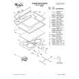
4 When DC is generated at the output because of a failure in the AMP system, etc.
A
5 When abnormally high temperature is detected by the thermistor
5 -1 IC81 abnormal temperature detection circuit
D
R3605 (R3625) (R3615) 27k Q3638 Front R ch (C, SR) R3606 (R3626) (R3616) 27k +
AF Assy
+5V
C
VD+5
6CH AMP Assy
IC81
VD+5 TH111 NCP18WF104J03RB
Q3632
E B
R108 27k
to XPROTECT
Front L ch (SW, SL)
A
XPROTECT
C
R113 220 R112 1k
Q111 2SC4081
R3638 10k
C3632 470/6.3
Q3637
Q3633
R111 1k
B
� In Normal mode, both Q3637 and Q3638 are off. (1) When positive (+) DC voltage is generated at the SP terminal When positive (+) DC voltage is generated at the L or R channel, and VB of Q3637 becomes higher than that at the operation point, Q3632 (E, C, B) is turned on, and the level of XPROTECT becomes low. � The microcomputer detects the XPROTECT level and shuts the power to the unit off. (2) When negative (-) DC voltage was generated at the SP terminal Q3638 is turned on, and XPROTECT is activated.
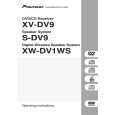
The voltage at Point A becomes the divided voltage of TH111 and R111//R112 (combined resistance of parallel-connected resistors R111 and R112.) In Normal mode, the resistance at TH111 is much higher than R111//R112, and Q111 is off. (Note that the resistance at TH111 becomes lower as the temperature increases.) If the solder temperature at IC81 increases abnormally, the temperature at TH111 (thermistor) mounted closest to the land of IC81 increases accordingly, and the resistance at TH111 decreases. When the temperature at TH111 reaches 90-110_C (varying according to conditions,) the voltage at Point (A) becomes high enough to turn Q111 on, and the level of the XPROTECT line becomes low. The microcomputer detects the XPROTECT level and shuts the power to the unit off. 5 -2 D22 abnormal temperature detection circuit If the solder temperature at D22 becomes abnormally high because of short-circuiting between AC - and +, or AC - and -, this protection circuit is activated.
VFL+5 D22 TH131 NCP18WF104J03RB
C
A
D
R131 560 1%
R133 220 R132 680 1%
to XPROTECT Q131 2SC4081
E
The voltage at Point A becomes the divided voltage of TH131 and R131//R132 (combined resistance of parallel-connected resistors R131 and R132.) In Normal mode, the resistance at TH131 is much higher than R131//R132, and Q131 is off. (Note that the resistance at TH131 becomes lower as the temperature increases.) If the solder temperature at D22 increases abnormally, the temperature at TH131 (thermistor) mounted closest to the land of D22 increases accordingly, and the resistance at TH131 decreases. When the temperature at TH131 reaches 107-125_C (varying according to conditions,) the voltage at Point (A) becomes high enough to turn Q131 on, and the level of the XPROTECT line becomes low. The microcomputer detects the XPROTECT level and shuts the power to the unit off.
F
116
1 2
XV-HTD640
3 4
|
|
|
> |
|