|
|
|
Categories
|
|
Information
|
|
Featured Product
|
|
|
 |
|
|
There are currently no product reviews.
 ;
I am very happy regarding the online purchase of this manual from Owner-Manuals.com as with this I could set right my Denon CD player and Amplifier.
I once again sincerely thank them for the prompt service which was rendered to me.
N. Shanker
;
More than pleased with my prurchase, very good product for the price.
;
Manual-link came 30 minutes after having paid for an extremely rare (40 years old) item (sony icr-120) and helped me to get the radio rework again. So really good help for me, fast and reliable delivery and -taken that into consideration- a very reasonable price for that service. So thanks again! Mike, Germany
 ;
Some of the pictures in this manual are a bit irritating. I had to dissassemble the unit and some of the screws have different threads, which is not mentioned in this manual. Also some of the drawings of the boards look different than the actual boards.
After all, the manual was very useful. I was able to recalibrate the capstan drive and it is working fine again.
;
This manual is very good. 303 pages scanned in a very high resolution. My camera has bad, leaking capacitors which all of the V5000 models are suffering from these days.
There is a huge part list with all capacitors, transistors etc. in this manual which helped me a lot. Otherwise I would not have been able to buy replacement parts.
The dissassembly guide is very enormous and detailed. Unlike on the Panasonic MS1 manual I downloaded here it actually looks like the real parts look. And the screws are labeled correctly, so you shouldn't have any left after the repair. ;)
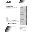
XV-E111SL/XV-E112SL
Removing the rear panel (see Fig.5)
*Prior to performing the following procedure, remove the top cover. 1.Remove the eight screws E attaching the rear panel on the back of the body. E Fig.5 Hook d F Hook c
Front panel assembly
Rear panel
E
E
Removing the front panel assembly (see Fig.6,7)
* Prior to performing the following procedure, remove the top cover. * There is no need to remove the mechanism assembly. 1.Remove the one screw F attaching the front panel assembly on the bottom chassis. 2.Disconnect the wire from CN702 and CN703 on the main board respectively.
Hook d Fig.6 CN702
Mechanism assembly 3.Hook c and d are removed respectively, and the front panel assembly is removed. CN703
Main board Fig.7
Removing the main board (see Fig.8)
* Prior to performing the following procedure, remove the top cover, mechanism assembly and rear panel. 1.Disconnect the wire from CN702 and CN703 on the main board respectively. 2.Remove the four screws G attaching the main board on the bottom chassis.
CN703
G Main board
G
CN702
G
Fig.8
G
1-7
|
|
|
> |
|