|
|
|
Categories
|
|
Information
|
|
Featured Product
|
|
|
 |
|
|
There are currently no product reviews.
 ;
This is the original manufacturers service manual, with detailed info on the circit boards, explosion drawings of all parts in assembly order, and tuning instructions. The only thing missing is the information on the dimensions of the various drive belts. mail me if you need them. gcrossman_at_aol.com
;
Ordered service manuel for a hard to find plasma tv - your company made it easy to find and purchase - I will use you again
Thanks for your help
 ;
This is a high quality manual with clear schematic and components layout diagrams ; with service procedure included.
;
This service manual for the Kenwood KT-990D was reproduced really well ,is very legible and manual is complete.Combined with the low price paid,in the future,I will be checking Owner-Manuals.com any time I need a manual.
;
When I purchased this manual I had my doubts regarding the quality as the price was so reasonable as compared to other outlets.
The manual itself is of high standard the print is very clear as are the diagrams. Obviously with the diagrams one has to zoom in otherwise it is to small to be able to read.
Overall I am very pleased with the company who delivered as they said and with the manual they supplied.
I occasionally require a manual and now having registered with this company I shall order from them in the future.
5
6
7
8
11 12 13 14
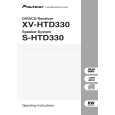
Remove the three screws. Remove the PCB support. Remove the flexible cable and disconnect the connector. Remove the DVDM Assy.
15 16
Connect the two jig cables. Reattatch the three flexible cables(A ) and the one connector (A) from the Table Mechanism Section.
A
17 12
PCB Support
Remove the soldered joint pickup short point. Reattatch the clamper holder by reattatching the two screws.
18
Flexible cable
Cutting Pliers
AF Assy
15
Jig cable (GGD1228)
B
13 13 11
CN923
14
A
13 11
CN5102 CN5101
11
CN911
C
15
DVDM Assy
Jig cable (GGD1160)
To DVDM CN923
To DVDM CN911
19 20
Insert the insulation sheet between the DVDM Assy and the chassis. Arrange the cables as shown in the photo below.
D
E
19
Insulation sheet
DVDM Assy
F
XV-HTD330
5 6 7 8
121
|
|
|
> |
|