|
There are currently no product reviews.
 ;
Excellent printing quality.
A complete and very usefull service manual with all details.
GREAT SERVICE AT VERY LOW PRICE!
A+++++++++++++++++++++++++
;
Excellent printing quality.
A complete and very usefull service manual with all details.
GREAT SERVICE AT VERY LOW PRICE!
A+++++++++++++++++++++++++
;
Excellent printing quality.
A complete and very usefull service manual with all details.
GREAT SERVICE AT VERY LOW PRICE!
A++
;
Complete service manual in excellent quality. I am very satisfied!
;
Complete service manual in excellent quality. I am very satisfied!
5
6
7
8
5 AF Assy
8
Reattatch the VIDEO JACK Assy by tighten the two screws.
8 �2
1 2 3 4 5
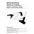
Remove the bonnet and tray cap. (See Step ¥.) Remove the Front Panel Section. (See Step ø.) Remove the Table Mechanism Section. (See Step �.) Remove the AMP Module Section. (See Step [.) Remove the DVD angle HTM by removing the two screws.
A
DVD angle HTM Rear view
5 5
DVDM Assy
B
9
10
Connect the two jig cables. Arrange the cables as shown in the photo below.
C
9
Jig cable (GGD1315)
9
Jig cable (GGD1315)
6
Remove the four screws. Rear view
6
CN3031 CN3032
D
CN3011 CN3012
6
6
6
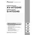
Note on handling the rear panel
During diagnosis, be sure NOT to remove the four screws marked A in the above photo. This unit will damage if the Audio Output connectors and the Speaker Output connectors of the AF Assy are separated from the rear panel, because that would damage the ICs in circuit. AMP TRADE Assy 6CH AMP Assy Rear view
E
A
Diagnosis
A
A
F
XV-HTD340
5 6 7 8
113
|