|
|
|
Categories
|
|
Information
|
|
Featured Product
|
|
|
 |
|
|
There are currently no product reviews.
 ;
This is a great site. I placed my order and by the next am it was available for download. Had some problems with some missing copy on some pages. Once I brought the error to the OMC's attention, the issue was resolved. I'll come back again.
 ;
Mi spiace per non poter scrivere in inglese... ma sono veramente soddisfatto del servizio offerto. Grazie..!!
;
The quality of this manual is good. It has all schematics and setup information for both the MDS-B3 and the MDS-B4. The scan quality is quite good, all pages are readable, This service manual also contains scans of the operating instructions from the User manual.
;
Quick site processing. A complete and very useful manual with all details. Thank you!
;
Das Service Manual war von der ersten bis zur letzten Seite sehr informativ und hilfreich. Die Darstellung aller Teile war klar und der Text gut lesbar.
Vielen Dank, das war nicht der letzte Download bei ownner-manuals.com.
1
2
3
4
A
11 12 13 14
Remove the three screws. Remove the PCB support. Remove the flexible cable and disconnect the connector. Remove the DVDM Assy.
15 16
Connect the two jig cables. Reattatch the three flexible cables(A ) and the one connector (A) from the Table Mechanism Section.
17 12
PCB Support
Remove the soldered joint pickup short point. Reattatch the clamper holder by reattatching the two screws.
18
Flexible cable
Cutting Pliers AF Assy DVD TRADE Assy
13
B
13 11
CN953
14
CN5105
15
CN5107
A
Jig cable (GGD1228)
13
C
11
CN911
11 15
DVDM Assy Jig cable (GGD1222) To DVDM To DVDM CN911 CN953
19 20
D
Insert the insulation sheet between the DVDM Assy and the chassis. Arrange the cables as shown in the photo below.
E
To CN5105
19
Insulation sheet
DVDM Assy
F
120
1 2
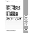
XV-HTD530
3 4
|
|
|
> |
|