|
There are currently no product reviews.
 ;
Very clear copy. No pages missing. Big bonus is that it includes supplement. Price is affordable compared to what others ask for.
;
Found the quality of the copy excellent and a very quick service. I would certainly recommend the service.
;
Good quality, clear diagrams. Exactly what I needed.
 ;
Good product. All the information is invcluded, but due to the complexity of the amplifier, it still is difficult to get it to operation again.
;
Very professional seller; very fast, accurate and rielable service.
1
2
3
4
A
11 12 13 14
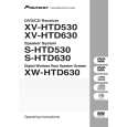
Remove the three screws. Remove the PCB support. Remove the flexible cable and disconnect the connector. Remove the DVDM Assy.
15 16
Connect the two jig cables. Reattatch the three flexible cables(A ) and the one connector (A) from the Table Mechanism Section.
17 12
PCB Support
Remove the soldered joint pickup short point. Reattatch the clamper holder by reattatching the two screws.
18
Flexible cable
Cutting Pliers AF Assy DVD TRADE Assy
13
B
13 11
CN953
14
CN5105
15
CN5107
A
Jig cable (GGD1228)
13
C
11
CN911
11 15
DVDM Assy Jig cable (GGD1222) To DVDM To DVDM CN911 CN953
19 20
D
Insert the insulation sheet between the DVDM Assy and the chassis. Arrange the cables as shown in the photo below.
E
To CN5105
19
Insulation sheet
DVDM Assy
F
120
1 2
XV-HTD530
3 4
|