|
|
|
Categories
|
|
Information
|
|
Featured Product
|
|
|
 |
|
|
There are currently no product reviews.
 ;
Very good manual, at a very good price. Received in a timely manner
;
Only thу cover has poor quality, internal material has excellent quality - exactly what I needed
Thanks!
 ;
Had everything I needed. Onyly took a few hours after paid for by PayPal. The copy was very readable.
;
Hi
First, thank you very much for the fast delivery.
I'm really satisfied with your manual. I could find everything, I needed.
I appreciate your service.
Regards from Germany PB
;
Everything you need: schematic, circuit explanation, operating/testing instructions. Awesome.
SECTION 2 ELECTRICAL ADJUSTMENTS
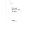
Equipment Use the following test equipment for alignment. � Oscilloscope dual trace, 10 MHz band or above with delay mode (use a 10 to 1 probe unless otherwise instructed.) � NTSC color bar generator � PAL color bar generator � DC power supply � Digital voltmeter � XT-61VE (TV tuner unit of XTL-610E) (XVM-61EX only) � Frequency counter Equipment Connections Make the test equipment connections as shown below (unless instructed otherwise) and perform the alignment. XVM-61EX :
NAVI INPUT (VIDEO) XT-61VE XVM-611EX
MONITOR SECTION
Voltage Adjustment Setting : DIMMER selector (S701) : HIGH BRIGHT dial (RV702) : Max. (light) VOL dial (RV301) : Max. Procedure : 1. Input the color bar (chroma off) signal from NTSC color bar generator and display on the monitor screen. 2. Connect the digital voltmeter to CL66 on the monitor main board. 3. Adjust RV401 (+5V) so that the digital voltmeter reads 5±0.1 V DC. 4. Connect the digital voltmeter to CL86 on the monitor main board. 5. Adjust RV601 (+9V) so that the digital voltmeter reads 8.5±0.1 V DC. Connection points : Monitor main board Refer to page 5. Alignment points : Monitor main board Refer to page 5. RGB Adjustment Procedure : 1. Input the color bar (chroma off) signal from NTSC color bar generator and display on the monitor screen. 2. Connect the digital voltmeter to CL151 on the monitor main board. 3. Adjust RV213 (OFFSET) so that the digital voltmeter reads 2.3±0.1 V DC. 4. Connect the oscilloscope to CL42 on the monitor main board. 5. Adjust RV212 (COM CUT) so that the lower black level is 6.2±0.05 V DC. 6. Adjust RV208 (COM DRIVE) so that the upper 100% white level is 9.2±0.05 V DC. 7. Repeat steps 5 & 6 until the items in the standards are satisfied. 8. Connect the oscilloscope to CL41 of the monitor main board. 9. Adjust RV207 (R DRIVE) so that the lower black level is 6.2±0.05 V DC. 10. Adjust RV202 (R CUT) so that the upper 100% white level is 9.2±0.05 V DC. 11. Repeat steps 9 & 10 until the items in the standards are satisfied. 12. Connect the oscilloscope to CL43 of the monitor main board. 13. Adjust RV209 (B DRIVE) so that the upper 100% white level is 6.1±0.05 V DC. 14. Adjust RV204 (B CUT) so that the upper 100% white level is 9.1±0.05 V DC. 15. Repeat steps 13 & 14 until the items in the standards are satisfied.
1 2 3 5 6 7 8 black level (8th step) 0V 4
color bar generator
VIDEO output (75 �)
MONITOR OUTPUT
XVM-6100 :
INPUT 1 (VIDEO) XA-601
color bar generator
MONITOR OUTPUT XVM-611
CONTROLLER VIDEO output (75 �) RM-X6100
white level (1st step)
Connection points : Monitor main board Refer to page 5. Alignment points : Monitor main board Refer to page 5.
�4�
|
|
|
> |
|