|
|
|
Categories
|
|
Information
|
|
Featured Product
|
|
|
 |
|
|
There are currently no product reviews.
 ;
Exactly what was needed to assess the product - excellent value and great service
;
A site where discontinualed schematic diagrams and back dated information can be found on discontinued radios tv's and any electronic equipment can be found. Newer manuals either Service and operating manuals. Radio amateurs should find this site a great source for ham radio equipment manuals. I will return to this site should I need information on any electrical equipment. priced easy to download in a PDF format and print pages need to undertake the repair.
;
Quality scan of the original. All the detail necessary to troubleshoot, repair and adjust the unit. I'm sure I will be downloading more manuals in the future as the need arises.
;
Exactly as described, a Service Manual complete with the schematics and PCB layout delivered in a timely manner. Many thanks for the great service.
 ;
some of the writing is a bit blur but the part in the schmatic was great and i have fixed the machine thanks
3.1.3 Removing the mechanism assembly (See Figure 2, Figure 5, Figure 6) � Prior to performing the following procedure, remove the top CN202 cover. C C CN101 � There is no need to remove the front panel assembly. (1) Insert a kind of screwdriver in a hole located in the right side of mechanism assembly, and push a lever until it cannot be inserted any further. (2) And then, a tray will come out. Remove the tray in an upper direction, with slightly opening the lower part of fitting in an outward direction. (3) Remove the three screws C attaching the mechanism assembly. (4) A tray is made to slide ahead. (5) A gear 1 is turned counterclockwise. Then, a pick-up unit Mechanism assembly C Main board moves back. CN201 (6) It solders to two c sections on the pick-up unit. Fig.5 (7) Disconnect the card wire from connector CN201, CN202, CN101 on the main board. ATTENTION: Please extract the wire after short-circuited of two places on the wire in part c with solder. Please remove the solder two places of part c after connecting the wire with CN101 when reassembling. CAUTION: Be sure to solder the short land sections �c� on the pickup unit before disconnecting the card wire from connector CN101 on the main board. If the card wire is disconnected without attaching solder, the pick-up unit may be destroyed by static electricity. (8) Remove the mechanism assembly by lifting the rear part of the mechanism assembly.
Gear1
Part c Pick-up Fig.6
(No.XA016)1-9
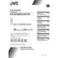 $4.99 XV-N310B JVC
Owner's Manual Complete owner's manual in digital format. The manual will be available for download as PDF file aft…
|
|
|
> |
|