|
|
|
Categories
|
|
Information
|
|
Featured Product
|
|
|
 |
|
|
There are currently no product reviews.
 ;
Complete MFG Service Manual at a good price FAST !
;
Downloaded the manual, reasonably straightforward, pretty much exactly as advertised.
 ;
very helpfull
circuit diagram and sparepart list available
;
Very good reproduction (copy) of original manual. Didn't have a parts list, but schematic was completely labeled with parts. Complete instructions on how to adjust mechanical functions of the 8-track deck. Well worth having and at a very reasonable cost.
;
It's a full manual. All the parts are in there. I haven't found the problem yett, but I am working on it; hope I can rebuild the part myself. To make it more secure and unbreakable this time. Because the part has failed several times before and costs a lot to let it be repaired.
Thanks so much for this rich illustrated and parted manual.
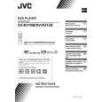
3.1.3 Removing the mechanism assembly (See Figure 2, Figure 5, Figure 6) � Prior to performing the following procedure, remove the top CN202 cover. C C CN101 � There is no need to remove the front panel assembly. (1) Insert a kind of screwdriver in a hole located in the right side of mechanism assembly, and push a lever until it cannot be inserted any further. (2) And then, a tray will come out. Remove the tray in an upper direction, with slightly opening the lower part of fitting in an outward direction. (3) Remove the three screws C attaching the mechanism assembly. (4) A tray is made to slide ahead. (5) A gear 1 is turned counterclockwise. Then, a pick-up unit Mechanism assembly C Main board moves back. CN201 (6) It solders to two c sections on the pick-up unit. Fig.5 (7) Disconnect the card wire from connector CN201, CN202, CN101 on the main board. ATTENTION: Please extract the wire after short-circuited of two places on the wire in part c with solder. Please remove the solder two places of part c after connecting the wire with CN101 when reassembling. CAUTION: Be sure to solder the short land sections �c� on the pickup unit before disconnecting the card wire from connector CN101 on the main board. If the card wire is disconnected without attaching solder, the pick-up unit may be destroyed by static electricity. (8) Remove the mechanism assembly by lifting the rear part of the mechanism assembly.
Gear1
Part c Pick-up Fig.6
(No.XA016)1-9
 $4.99 XV-N312S JVC
Owner's Manual Complete owner's manual in digital format. The manual will be available for download as PDF file aft…
|
|
|
> |
|