|
|
|
Categories
|
|
Information
|
|
Featured Product
|
|
|
 |
|
|
There are currently no product reviews.
 ;
The manual for Sony LBT-D505 component stereo system is was excellent , with schematics, parts layout and parts list as well as instructions for adjustments for each component. Print was clear even when enlarged.
;
It's exactly a complete and very useful manual with all details what I needed. Thank you!I will come back whenever I need your manuals or schematics.
;
I searched EVERYWHERE looking for the manual/s on this "extinct" amp. Owner-Manuals.com made it available and for nearly nothing. Thanx to them, I can decipher the unknown cables and sort them out. Thanx, Owner-Manuals.com!!
;
Yes thank you i got the file i was after. There was a slight problem in my communication but it all worked out well.
A job well done.
 ;
Great manual...really saved me. The only problem is that I thought I would be able to download it directly when I paid for it but never received the download instructions until the next morning. The board trace pages were somewhat light also: really need to turn up the contrast on the printer before printing them. The schematic page was great; very clear! Well worth the money.
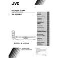
XV-S200BK/XV-S300BK/XV-S302SL XV-S400BK/XV-S402SL
Removing the rear panel (see Fig.5)
*Prior to performing the following procedure, remove the top cover. 1.Remove the seven screws D attaching the rear panel on the back of the body. * As for the screw D, the number and the position are different according to the destination and model. E D D Fig.5 Hook d Hook c
Front panel assembly
Rear panel
D
Removing the front panel assembly (see Fig.6,7)
* Prior to performing the following procedure, remove the top cover. * There is no need to remove the mechanism assembly. 1.Remove the one screw E attaching the front panel assembly on the bottom chassis. 2.Disconnect the wire from CN702 and CN703 on the main board respectively.
Hook d Fig.6
Mechanism assembly 3.Hook c and d are removed respectively, and the front panel assembly is removed. CN702
CN703
Main board Fig.7
Removing the main board (see Fig.8)
* Prior to performing the following procedure, remove the top cover, mechanism assembly and rear panel. 1.Disconnect the wire from CN702 and CN703 on the main board respectively. 2.Remove the four screws F attaching the main board on the bottom chassis.
CN702
F
Main board
F
CN703
F
Fig.8
F
1-7
|
|
|
> |
|