|
There are currently no product reviews.
 ;
The purchased manual is an high quality scan of the original Philips paper-based Service Manual. I am very satisfied!
 ;
The purchased manual is an scan of the original Panasonic paper-based Service Manual. Unfortunately the contrast is not perfect, but I am satisfied anyway!
;
The purchased manual is an high-quality scan of the original JVC paper-based Service Manual. The Service Manual includes the Owner´s Manual, so you do not have to buy both of them.
;
It paid to find this Service Manual, couldn't find it anywhere else. Exactly what I wanted. Received within 24 hours.
;
Complete manual with clear schematic diagrams and printed circuit board layouts of two variants of the headset and the transmitter an old and a new version.
Also shows how the headset and the transmitter is opened and how transmitter and receivers can be adjusted and where to measure.
I had no problems to repair the headset using this service manual.
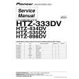
3.3.6 Removing the amp. board (See Fig.10) � Prior to performing the following procedures, remove the amplifier assembly, rear panel, heat sink BKT and mother board. (1) From the left side of the amplifier assembly, remove the nine screws J attaching the amp. board. (2) Take out the amp. board with the heat sink.
Amp. board
Heat sink
J
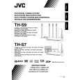
Fig.10 3.3.7 Removing the heat sink (See Figs.11 and 12) � Prior to performing the following procedures, remove the amplifier assembly, rear panel, heat sink BKT, mother board and amp. board. (1) From left side of the amp. board, remove the screw K attaching the hold spring to the heat sink. (See Fig.11.) (2) Remove the four screws L attaching the power IC to the heat sink. (See Fig.11.) (3) From the reverse side of the amp. board, remove the three screws M attaching the heat sink to the amp. board. (See Fig.12.) (4) Take out the heat sink. 3.3.8 Removing the power IC (See Fig. 12) � Prior to performing the following procedures, remove the amplifier assembly, rear panel, heat sink BKT, mother board, amp. board and heat sink. (1) From the reverse side of the amp. board, remove the solders from the solder points a on the amp. board. (2) Take out the power IC.
Heat sink
Power IC
Amp. board
L
Hold spring
Fig.11
L K
Amp. board
Solder points a
M
Fig.12
1-22 (No.MB236)
 $4.99 XV-THS7 JVC
Owner's Manual Complete owner's manual in digital format. The manual will be available for download as PDF file aft…
|