|
|
|
Categories
|
|
Information
|
|
Featured Product
|
|
|
 |
|
|
There are currently no product reviews.
 ;
I'm happy. Good quality. Very helped me with my work..............................
;
This is the second Manual I have ordered from owner-manuals, I give it five stars because it is exactly what I expected given the age of the equipment. So the contents look a bit aged and the pictures a bit grainy, it fulfills my needs and I am glad I can still get hold of them.
;
thank u so much for this manual that was so cheap that i thought it was a scam but i gambled anyway because it was too good of a deal to pass up and behold,the manual has everything and details of everything even the screws and im still amazed and very happy with my manual .so take my word and jump on it before they realize how cheap they selling thier manuals..thank you so much for taking time to read my thoughts
 ;
I do not have very much to say.
The price is quite covenient, delivery was better as promised (about 12 ours, against the specified 24 hours if I remember well), and the quality of the PDF is more than acceptable.
The Service Manual of Sansui R30 itself is also satisfactory: good graphic for schematics and layouts, simple and well structured.
Giovanni Bianchi
;
Happy to find finally a schematic for this amplifier. The schematic is of good quality, the pcb layout is useless: all is black. Never the less, it is very easy to find the components on the board using the schematics.
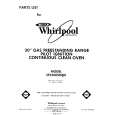
3.1.8 Removing the power board (See Figs.10 and 11) � Prior to performing the following procedures, remove the top cover assembly or metal cover. (1) From the back side of the main body, remove the screw M attaching the power board to the rear panel. (See Fig.10) (2) From the top side of the main body, disconnect the parallel wires from the connectors (CN404 to CN407) on the main board. (See Fig.11) (3) Remove the three screws N attaching the power board. (See Fig.11) (4) Take out the power board from the main body. Reference: When attaching the power board on the chassis base, align the projection d of the chassis base in the hole of the power board. (See Fig.11.)
Rear panel
M
Fig.10
N
CN407 CN406 Main board
d
CN404
CN405
N
Fig.11
Power board
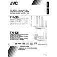
3.1.9 Removing the main board (See Figs.12 and 13) � Prior to performing the following procedures, remove the top cover assembly or metal cover, audio signal I/O board and tuner. (1) From the back side of the main body, remove the seven screws P attaching the rear panel. (See Fig.12.) (2) Release the engagement sections e and remove the rear panel from the main body. (See Fig.12.) (3) From the top side of the main body, disconnect the card wires from the connectors (CN401 to CN403, CN408, CN409, CN451, CN452) on the main board. (See Fig.13.) (4) Disconnect the parallel wires from the connectors CN404 to CN407 on the main board. (See Fig.13.) (5) Remove the spacers fixing the card wires on the main board. [For XV-THS9, XV-THS7 models] (See Fig.13.) Reference: After attaching the main board, fix the card wire with the spacers as before. (6) Remove the three screws Q attaching the main board on the main body. (7) Take out the main board from the main body.
Rear panel
e
e
P
Fig.12
CN406
P
CN407 Spacer
P
Spacer CN408
P
CN405 CN404
CN452
CN401 CN403 CN409 CN402 CN451
Main board
Fig.13 1-12 (No.MB236)
 $4.99 XV-THS8 JVC
Owner's Manual Complete owner's manual in digital format. The manual will be available for download as PDF file aft…
|
|
|
> |
|