|
|
|
Categories
|
|
Information
|
|
Featured Product
|
|
|
 |
|
|
There are currently no product reviews.
 ;
The manual is excellent, well detailed, and divided into two parts. Received very quickly. Thank you.
;
a solid deal - quick and without any problems.
I life in europe - with downloads no loosing time
once again
 ;
got exactly what i ordered in a very timely manner. will use again for other manuals
;
I'm happy. Good quality. Very helped me with my work..............................
;
This is the second Manual I have ordered from owner-manuals, I give it five stars because it is exactly what I expected given the age of the equipment. So the contents look a bit aged and the pictures a bit grainy, it fulfills my needs and I am glad I can still get hold of them.
XV-Z7000U/E
AN-Z7T
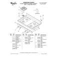
5. Ausbau der Ballast-/Leistungs-/Netzeingangseinheit-Platine, des Kühlgebläses und des Spannungswählschalters
5-1. Die Halteschraube (gelb oder silberfarben) aus der Ballast-Abdeckung herausdrehen. Das Teflon-Klebeband entfernen, das zur Befestigung der Steckerkabel an der Ballast-Abdeckung dient. Die Ballast-Abdeckung herausnehmen. 5-2. Die drei Halteschrauben (gelb oder silberfarben) aus der Ballast-Platineneinheit herausdrehen. Die Stecker aus der Leistungs-Platineneinheit herausdrehen, dann die Ballast-Platineneinheit entfernen. 5-3. Die beiden Halteschrauben (silberfarben) aus der Kühlgebläse-/Leistungs-Platineneinheit entfernen, dann die Kühlgebläse-Einheit ausbauen. 5-4. Die drei Halteschrauben (silberfarben) aus der Netzeingangs-/Leistungs-Platineneinheit herausdrehen. Die Stecker des Spannungswählschalters und der Leistungs-Platineneinheit (EA) abziehen. Die Netzeingangs-Platineneinheit, Leistungs-Platineneinheit und die Abdeckung der Leistungs-Platineneinheit herausnehmen. 5-5. Die beiden Halteschrauben (gelb) aus dem Spannungswählschalter herausdrehen, dann den Schraube, das Gleitstück und die Feder entfernen.
Ballastabdeckung
5-1
5-1 Teflon-Klebeband
5-2
Ballast-Platine
(
Hinweis: Beim Anschlu§ dieses Steckers besonders vorsichtig vorgehen, da die benachbarten Teile der Ballast-Platineneinheit stromf hrend sind.
)
Eingangsplatinen-Einheit
K hlgebl se 5-3 B A
5-4 5-5
5-4 Leistungsplatinen-Einheit Spannungs w hlschalter Gleitst ck Abdeckung der LeistungsplatinenEinheit Feder
�Vorsichtshinweise zum Zusammenbau Die Hochspannungskabel ( A und B in der Abbildung) der Lampenfassung an der Ballast-Platineneinheit dürfen nicht mit dem Kühlgebläse in Kontakt kommen. Um dies sicherzustellen, ist das Kabel B hinter Kabel A zu verlegen, dann die Kabel in den Einschnitt des Kühlgebläse-Halters einpassen.
57
|
|
|
> |
|