|
|
|
Categories
|
|
Information
|
|
Featured Product
|
|
|
 |
|
|
There are currently no product reviews.
 ;
Everything fine: quick service, no glitch and above all a very good quality of the Pdf file. Thank you!
;
The manual was complete, parts list, adjustment procedures, etc. No worries
 ;
Very usefully, I could find the trouble clearly with that manual.
;
Bon produit. Permet de corriger les couleurs et de redonnez un petit coup de jeune à vos vieilles vidéos. On regrettera juste le manque d'une prise s-vidéo.
;
Quality scan of the actual service manual, just what I was looking for.
XV-Z9000U/E
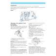
When the DMD unit has been replaced
Note: DMD chip and Formatter PWB are supplied at the same time, and an exchange only with DMD isn't done.Refer to "REMOVING OF MAJOR PARTS" when exchanging Formatter PWB. There is no need to readjust the back focal distance of the projection lens. If focusing is noticeably poor, however, make this readjustment. (1) (2) (3) (4) (5) (6) (7) Provide a distance of 2.4 m between the set and the screen. Adjust the lens shift until the projection lens comes to the same level as the center of the screen. Detach the optical unit top cover A from behind the projection lens. Loosen the four hex screws B in the back of the projection lens. Adjust the zoom knob at the front of the projection lens to �tele end� and ensure good focusing. Then adjust the zoom knob at the front of the projection lens to �wide end�. Insert the adjustment screwdriver C (9EVDRIVERZ9000) in the hole D at the back of the lens. Put the center of the screen in the best focus. (Preferably feed the SXGA signal for 1-dot white crosshatch pattern or 1-dot white dot pattern on black background.) (8) Move the zoom knob from �wide end� back to �tele end� and see if focusing is ensured. If not, repeat the above steps (5), (6) and (7) until the best focus is achieved. (9) Tighten the four hex screws B to the torque of 0.3 Nm (3.06 kgfcm), and apply screw loctite to them. (10) Attach the optical unit top cover A back into position. Finally fix the two screws E and apply screw loctite to them.
E E
A
C
X
B D
B
B B
Expansion figure of part X
23
|
|
|
> |
|