|
|
|
Categories
|
|
Information
|
|
Featured Product
|
|
|
 |
|
|
There are currently no product reviews.
 ;
Thought I would never find a copy of the Technics SX-EN2 Service Manual until I found Owner-Manuals.com. Price was very fair and I received the download promptly. While a photocopy, it is quite readable and includes all the pertinent information and diagrams. Thank you Owner-Manuals!
 ;
I really like this manual and it's reliable.I found and bought easly.thank you.
;
Thank you very much. the Instruction corresponds to my expectations. Sent it in time. I don't regret that paid money.
;
Good quality. Quick service. I recommend to everyone.
;
Very good quality scan of the document. I am very pleased with what I got.
1
2
3
4
7.1.2 NOTES ON REPLACE OF PARTS
A
(ID-related) The ID number for an individual product is stored in the EEPROMs (U7 for the TX module, U11 for the RX module) of each module (TX module: AXF7006, RX module: AXF7008). It should be noted that wireless communications cannot be performed unless these ID numbers are identical.
1. Replacement of the TX or RX module
Upon replacement of the TX (AXF7006) or RX (AXF7008) module, remove the EEPROM from the original module and mount it on the new one.
2. Replacement of the EEPROMs (U7 and U11)
Using service part AXX7169 (a kit containing two EEPROMs with identical ID numbers stored in them,) replace both EEPROMs when either needs to be replaced.
B
Note : The AXX7169 is a service part containing two EEPROMs, both of which must be replaced when either needs to be replaced.
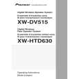
7.1.3 DIAGNOSIS OF THE AMPLIFIER SECTION
You can diagnose the amplifier section even if the transmitter section is not available. Input audio signals to the Jumper Wire for service use indicated below. At that time remove the RX MODULE.
W141 LW142 L+
C
W155 R-
VA+9 13 CN3051 1
1 pin
B MAIN ASSY
SIDE A
1 3
Jumper Wire for service for signal input
W127 VREF Ch.SEL
CN3701
W195 W194 W139 W193
L GND R
1 4
W156 R+
W143 GNDP
W126
E
W140 V+9RF
F
60
1 2
XW-HTD630
3 4
3401
4 1
D
PNE-1B1
CN5
CN5901
1
1 12 1 1 12 1 2 13
3
servicefor
Wh
|
|
|
> |
|