|
|
|
Categories
|
|
Information
|
|
Featured Product
|
|
|
 |
|
|
There are currently no product reviews.
 ;
I needed the manual immediately and I got it immediately. I couldn't find this manual anywhere else on the net. The site was easy to traverse, and the price was very reasonable. I'll definitely be back for any future needs.
 ;
I received a good service manual, with good resolution. Improve the instructions for the purchase because they are not well understood.
For the rest, so good.
Thanks Angel.
 ;
Very good documentation for the Grundig 2077 model (as well as similar 800/900/1000 series radios). The first two pages are a summary of reception specifications and output capability. The third page is the tuner dial indicator and dial cord routing diagram. the final ~5 pages are the schematics for the various models (including 2077). The scan quality of the schematics are good, adn can be easily read if zoomed in. The documents are in German, not English as stated. It would have been nice to have the tuning sequence and settings, and some trouble shooting materials... or component and wiring map.
 ;
Perfect like it was descriped, Perfect like it was descriped
 ;
Very good detail, all pages clear, exactly what I needed
(V)
V1
CLV
0V
60Hz
50Hz
a
V2 Pulse ON time 0V
CPU output (CLPWM)
(msec)
�
V3
The shorter the pulse ON time is, the higher the CLV is, and vice versa. The pulse ON time rises at the zero-cross timing of AC and is driven with duty. Positive pulses the copy lamp ON signal are generated by C248 (C253) at falling of the CPU output and inputted to the photo triac through the 2-stage transistors.
�
0V
�
b
+5V
(11) Power section
This model is provided with the auto shut-off mode. The power section is also designed for it. When the power switch of the copier is turned on and the AC power is supplied, AC waveforms for +5V power are generated in the secondary side of transformer T301. The AC waveforms are full-wave-rectified and smoothed by diode BD102 on the main PWB side, and 5V is generated by 3-terminal regulator of IC111. The 5V power is supplied to the CPU. When the CPU is actuated by the 5V power, it starts the switching power to output the SWPEN signal (CPU output: LOW). The switching power outputs voltages of 24V and VBS with this signal. BVS is stabilized by IC112 to become a voltage with stable BV, and is used for LED display. 24V is supplied to the motor and the solenoid, and supplied also to the 3-terminal power for 5V through D144. When the CPU turns off SWPEN to enter the auto power shut-off mode, 24V and VBS output falls near zero, virtually turning off.
V4 0V
V5
0V
VCL
0V
Main switch (MSW)
T301
Main PWB
BD102 SINB60
IC111 7805
5V C107 47µF
C111 2200µF
* At rising of the CLPWM signal (V4), the coy lamp is switched by the triac. The trigger signal Cl is sent to the triac to turn on the lamp. Then the lamp is turned off at the zero-cross point of V1 waveform. The CPU reads the control voltage level (QV) corresponding to the change in the copy lamp voltage The CLV produces the waveform equivalent to the copy lamp voltage waveform which disables the full-rectified waveform of AC input during the pulse ON time. The waveform is converted to the DC level by the low pass filter composed of C102 and R105, and inputted to the CPU. The relationship between the CLV and the pulse ON time is shown in the figure below.
AC PWB
DC power unit
24V
D144 1N4004E
GND V8S IC112 7808 5V
1SWPEN
8V C105 47µF
IC101 CPU
DTC123JKA
C106 47µF
8 or 10 msec
Q209
Pulse ON (Varies)
12 � 10
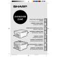
 $4.99 Z-810 SHARP
Owner's Manual Complete owner's manual in digital format. The manual will be available for download as PDF file aft…  $4.99 Z810 SHARP
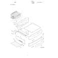
Parts Catalog Parts Catalog only. It's available in PDF format. Useful, if Your equipment is broken and You need t…
|
|
 |
> |
|
