Having bought a pre-owned Sony FM stereo tuner through eBay, it came without any manuals. It soon became clear that to get the best from this excellent tuner I needed a decent manual because much of the operation was not intuitive to a newboy to hi fi like me. I managed to download the official Sony multi-lingual manual from Owner-Manuals.com with no problem at all - a really quick and easy service. I'm very glad I did because I found out all the operations of the tuner and was then able to not only set it up quickly but also to get much more from it that poke-and-hope trialling would ever achieve. In my book $4.99 very well spent.
This manual is immaculate in it's accuracy. Everything is written very clearly and easy to understand. Written by a professional who wants to convey a clear and easy to understand message!!
Great site, I always find all the manuals I need and i can't find anywhere else. PDF for the Sony PCM 3348 is complete and scan is good quality. Thank you!
Text excerpt from page 32 (click to view)
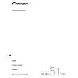
300 mm.
WALL FACE
BACK OF COOKER
100 mm.
LEVELLING FEET
ENGAGEMENT EDGE FOR STABILITY BRACKET BASE OF COOKER
580 mm.
A
PENCIL LINE ON THE FLOOR 295 mm.
FO 0179
PLAN VIEW OF THE COOKER
SIDE VIEW OF THE COOKER
Fig. 2
Fitting the Stability Bracket (Not supplied)
If the cooker has to be installed with a flexible supply pipe, it is necessary that a stability device is fitted. (See "Important Safety Requirements"). The stability bracket should be fitted by the installer and these instructions should be read in conjunction with the leaflet packed with the stability bracket. Place cooker in its intended position and level cooker. Mark off 295mm (11 / ") from the right hand side of the cooker as shown, this is the centre line of the bracket fixing. Draw a line 100mm (4") from the front edge of the levelling feet (see Fig. 1) and remove cooker from its position. Mark off 580mm (23") back from this line on the centre line of the bracket to locate the front edge of the lower bracket. Fix lower bracket (with two fixing holes) to the floor, then measure height from floor level to engagement edge on back of cooker, dimension 'A' of Fig. 2. Assemble upper bracket to lower bracket so that underside of bracket is dimension 'A' +3mm (1/8") above floor level. Re-position cooker and check that top bracket engages into cooker back to a depth of 75mm (3"), as shown in Fig. 2. Should the stability bracket currently installed not allow the cooker to stand correctly, ask the installer to replace it with the correct type.
2 1
Connecting to Gas
This cooker is designed to be installed with an appliance flexible connection. Connection is made to the RC 1/2 (1/2" B.S.P.) threaded entry pipe located just below the hotplate level on the rear right-hand side of the cooker. Check for gas soundness after connecting the gas supply. The gas bayonet connector must be fitted in the shaded area indicated in Fig. 3. Take into account that it must be possible to pull the cooker forward sufficiently. The hose must not get caught on the stability bracket. Note: If using different types of gas bayonet connection, it may not be possible for the appliance to be pushed fully back to the wall stops. Important: Flexible tubing MUST comply with BS.669 Current Edition.