I am very happy with the owner's manual. I bought a used Casio and was so relieved that I was able to get a hold of a owner's manual. It was very easy to download the manual and I had no problems with printing it. Thank you! Nancy Whalen
great site, the most easy and fastest way to find the manual you need, no 5 star because the manual was only available in german, but I speak german as well so no problem for me.
thanks for this download i got a pioneer bdp-lx70a blu-ray player and it had no manual i search everywhere on the internet and came across owner-manuals.com and i found that it was so easy to find and downloaded from this site if i ever need a manual again this would be the first place that i would come too thanks guys
Text excerpt from page 15 (click to view)
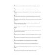
INSTALLING THE COOKER HOOD
Fitting the Wall Brackets
7.2.1
11 12a
116 116 X
Wall marking: � Draw a vertical line on the supporting wall up to the ceiling, or as high as practical, at the centre of the area in which the hood will be installed. � Draw a horizontal line at 650 mm above the hob. � Place bracket 7.2.1 on the wall as shown about 1-2 mm from the ceiling or upper limit aligning the centre (notch) with the vertical reference line. � Mark the wall at the centres of the holes in the bracket. � Place bracket 7.2.1 on the wall as shown at X mm below the �rst bracket (X = height of the upper chimney section supplied), aligning the centre (notch) with the vertical line. � Mark the wall at the centres of the holes in the bracket. � Mark a reference point as indicated at 116 mm from the vertical reference line and 306 mm above the horizontal reference line. � Repeat this operation on the other side. � Drill ø 8 mm holes at all the centre points marked. � Insert the wall plugs (not supplied) in the holes. � Fix the lower bracket 7.2.1 using the two screws (not supplied). � Fix the upper bracket 7.2.1 and the air outlet connection support 7.3 together using the two screws (not supplied). � Insert the two screws (not supplied) in the hood body �xing holes, leaving a gap of 5-6 mm between the wall and the head of the screw. Note: If the hood is to be installed onto a hollow construction or plaster or partition board wall then special �xing screws will be required (not supplied).