|
|
|
Categories
|
|
Information
|
|
Featured Product
|
|
|
 |
|
|
There are currently no product reviews.
 ;
Veramente completo, dettagliato e perfetto nella visione. Perfect, thanks!
 ;
Fully functional usable service manual. Considering the age of the manual and device quality was better than expected
;
Thank you very much, I've been very happy to find this manual on "Owner Manual". It's a perfect copy and it has been really useful for my work!
;
It took about 24-hours after my payment before I was able to get to the download. Apparently, payment processing is not 100% automated. That is no big deal, just be aware of that going in.
After I got to it, it was in good shape, easy to read, etc. Not some cheap FAX copy looking thing.
Also, this site was the cheapest I found. Another Plus!
;
Good price, very legible manual, exactly what I needed -- but had to wait a day to actually get the download of the manual. Would have preferred to download it immediately after payment rather than waiting for someone to "process" my order. I was surprised that I had to wait that long.
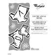
B MICON C.B
FL101
L101
IC101 TP7 (O-KSCAN)
D-GND
14
14
DECK�1 P HEAD DECK-2 R/P/E HEAD K DECK C.B
SFR1
9 9
8
< DECK SECTION >
8. Tape Speed Adjustment (DECK 2) Settings : � Test tape : TTA�100 � Test point : TP8 (Lch), TP9 (Rch) � Adjustment location : SFR1 Method : Play back (FWD) the test tape and adjust SFR1 so that the frequency counter reads 3000Hz ± 5Hz and ± 45Hz (REV) with respect to forward speed. 9. Head Azimuth Adjustment (DECK 1, DECK 2) Settings : � Test tape : TTA�330 � Test point : TP8 (Lch), TP9 (Rch) � Adjustment location : Head azimuth adjustment screw Method : Play back (FWD) the 8kHz signal of the test tape and adjust screw so that the output becomes maximum. 10. PB Frequency Response Check (DECK 1, DECK 2) Settings : � Test tape : TTA�330 � Test point :TP8 (Lch), TP9 (Rch) Method : Play back the 315Hz and 8kHz signals of the test tape and check that the output ratio of the 8kHz signal with respect to that of the 315Hz signal is within 5dB. 11. PB Sensitivity Check (DECK 1, DECK 2) Settings : � Test tape : TTA�200 � Test point : TP8 (Lch), TP9 (Rch) Method : Play back the test tape and check that the output level of the test point is 230mV ± 3dB. 12. REC/PB Frequency Response Adjustment (DECK 2) Settings : � Test tape : TTA�602 � Test point : TP8 (Lch), TP9 (Rch) � Input signal : 1kHz / 10kHz (LINE IN) � Adjustment location : SFR351 (Lch) SFR352 (Rch) Method : Apply a 1kHz signal and REC mode. Then adjust OSC attenuator so that the output level at the TP8, TP9 becomes 0dB (16mV). Record and play back the 1kHz and 10kHz signals and adjust SFRs so that the output of the 10kHz signals becomes 0dB ± 0.5dB with respect to that of the 1kHz signal. 13. REC/PB Sensitivity Check (DECK 2) Settings : � Test tape : TTA�602 � Test point : TP8 (Lch), TP9 (Rch) � Input signal : 1kHz (LINE IN) Method : Apply a 1kHz signal and REC mode. Then adjust OSC attenuator so that the output level at TP8, TP9 becomes 0dB (160mV). Record and play back the 1kHz signals and check that the output is 0dB ± 3.5dB.
< FRONT SECTION >
14. MICON OSC Adjustment Settings : � Test point : TP7 (O-KSCAN) and D-GND � Adjustment location : L101 Method : Pull out AC plug, then insert AC plug again with pressing of TUNER / BAND function key and POWER key. Adjust L101 so that the frequency across the test point is 208.80Hz ± 0.21Hz or 4.78ms ~ 4.79ms.
� 35 �
|
|
|
> |
|