|
|
|
Categories
|
|
Information
|
|
Featured Product
|
|
|
 |
|
- SPECIFICATIONS
- EXTERNAL DIMENSIONS
- WIRING DIAGRAMS
- ELECTRICAL PARTS
- BLOCK DIAGRAM
- MICROCOMPUTER CONTROL SYSTEM
- FUNCTIONS
- FUNCTION AND OPERATION OF PROTECTIVE PROCEDURES
- BREAKDOWN DIAGNOSIS PROCEDURE
- REFRIGERATION CYCLE
- PERFORMANCE CURVES
- DISASSEMBLING PROCEDURE
- OPTION
- REPLACEMENT PARTS LIST
There are currently no product reviews.
 ;
Manual was reasonably easy to follow. I am not an engineer or know much about electronics but with the manuals help I was able to figure out the problem, identify the part required for the repair. Replacement part cost around $30. Whilst replacing the part I was telling myself, "this aint gonna work cos it seems far too easy". Took about 15 minutes to do and my plasma TV works a treat. Would never have been able to do this without the service manual.
;
It is OK, this manual help me to repair my dynacord
 ;
Good manual. Even it is an old printed manual, it is well scanned and complete, with all drawings, schematics and parts list. Very good return for the cost.
;
I'm very satisfied with my purchase. It resolved my problem. Owner-manuals.com is a very very good place.
Thank you!
;
Veramente completo, dettagliato e perfetto nella visione. Perfect, thanks!
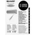
AY-XP08/10/13CE AE-X08/10BE-C AE-X13BE
CN101 and CN102
How to remove the horizontal louver Slightly pull down the hinge area, deflect the louver, and unhook it from the hinge. Remove the shaft from each of the left and right sides.
5. Remove 2 connectors. How to remove the HI VOLTAGE UNIT. 1. Remove the HIGH VOLTAGE UNIT.
6. Pull the board. Drain pan and related (Press and spread the hook, and HI VOLTAGE will be ready for removal.) How to remove the DUST SENSOR, the THERMISTOR and the GAS SENSOR. Remove the DUST SENSOR, the THERMISTOR, and the GAS SENSOR.
DUST SENSOR GAS SENSOR
1. Remove 3 screws fixing motors.
Drain Hose
THERMISTOR
Drain pan Groove
Projection
(Press and spread the hook,and GAS SENSOR will be ready for removal) How to remove the display board unit 2. The display board unit 2 is pushed in the direction of arrow 1 . And it is made to slide in the direction of arrow 2 , and remove.
1 2
To disconned
To reconnect
2. Turn the cap area of the drain hose counterclockwise, and remove it from the drain pan. During installation, turn the drain hose to the state of the �engagement position�. After reinstallation, verify that it is securely fastened.
display board unit2
38
|
|
|
> |
|