|
|
|
Categories
|
|
Information
|
|
Featured Product
|
|
|
 |
|
|
There are currently no product reviews.
 ;
It was very usefull, it is clear the quality is super, the price I paid is very afordable.
Generally speaking Iam very happy with this company.
;
The manual was exactly what I needed, Good quality scans too. superb.
;
I am so happy found this site as it consists of so many Manuls and easy to aquire. This onei s exactly what I wanted and much more as it has info on not only how to use the tuner but how to repair it as well. I will come here 1st before purchasing else where! Thanks owner-manual.com!
;
Top class product, I printed it out on A3 paper and it is clear and very easy to follow.
Cheaper than buying a new radio!
;
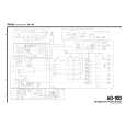
is part of the manual is very useful for repairing
Here are circuit diagrams
if there is damage, I recommend using this part of the
a complete list of circuit boards and components
2 ADJUSTMENTS AND CHECKS
2-1 Equipment Requried
�AM Standard Signal Generator (AM SSG) �FM Standard Signal Generator (FM SSG) �Oscilloscope �AC Voltmeter �Audio Generator �Stereo Modulator �Distortion Meter �DC Voltmeter
Note : Disconnect external FM antenna prior to adjustment.
2-2 Adjustment Locations
FD1 SVR03
IF COIL SVR01 SVR02 OSC COIL
EC1
JW10
ANT COIL
TUNER PCB
R17 (Pattern Side)
2-3 AM Adjustment
�Output of signal generator should not be greater than necessary to obtain an optimum output reading. �Signal generator modulation : 30% �Signal frequency : 400Hz �Modulation frequency : 600kHz, 1000kHz, 1400kHz [US,C] / 603kHz, 999kHz, 1404kHz [E,UK,K] ITEM SIGNAL GENERATOR SETTING 520kHz / 1710kHz [US,C] 522kHz / 1611kHz [E,UK,K] 600kHz [US,C] 603kHz [E,UK,K] SET FREQUENCY SETTING 520kHz / 1710kHz [US,C] 522kHz / 1611kHz [E,UK,K] 600kHz [US,C] 603kHz [E,UK,K] EQUIPMENT CONNECTION ADJUSTMENT POINTS ADJUST FOR 520kHz : 1.2 ± 0.1V 1710kHz : 7.0�8.5V 1611kHz : 7.2�8.5V
1. Tunning Voltage
JW10 DC Voltmeter
OSC COIL
2. IF Tracking
TAPE PLAY terminal AC Voltmeter Oscilloscope TAPE PLAY terminal AC Voltmeter Oscilloscope TAPE PLAY terminal AC Voltmeter Oscilloscope �3�
IF COIL
Maximize audio output
3. RF Tracking
600kHz [US,C] 603kHz [E,UK,K]
600kHz [US,C] 603kHz [E,UK,K]
ANT COIL
Maximize audio output Repeat LOW,HIGH frequency
4. Seek Level
600kHz [US,C] 603kHz [E,UK,K]
600kHz [US,C] 603kHz [E,UK,K]
SVR03
Tuned on point
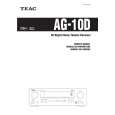 $4.99 AG-10D TEAC
Owner's Manual Complete owner's manual in digital format. The manual will be available for download as PDF file aft…
|
|
|
> |
|