|
|
|
Categories
|
|
Information
|
|
Featured Product
|
|
|
 |
|
|
There are currently no product reviews.
 ;
The manual for Sony LBT-D505 component stereo system is was excellent , with schematics, parts layout and parts list as well as instructions for adjustments for each component. Print was clear even when enlarged.
;
It's exactly a complete and very useful manual with all details what I needed. Thank you!I will come back whenever I need your manuals or schematics.
;
I searched EVERYWHERE looking for the manual/s on this "extinct" amp. Owner-Manuals.com made it available and for nearly nothing. Thanx to them, I can decipher the unknown cables and sort them out. Thanx, Owner-Manuals.com!!
;
Yes thank you i got the file i was after. There was a slight problem in my communication but it all worked out well.
A job well done.
 ;
Great manual...really saved me. The only problem is that I thought I would be able to download it directly when I paid for it but never received the download instructions until the next morning. The board trace pages were somewhat light also: really need to turn up the contrast on the printer before printing them. The schematic page was great; very clear! Well worth the money.
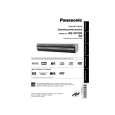
AG-VP320
5.1.1.1.
Notes in chart (Cabinet Section)
1. Removal of Top Panel a. Remove the 7 screws (501, 502). b. Raise the rear portion of Top Panel, and insert your hand in the inside and lift the position �A� to release the Top Panel from Locking Portion.
Fig. C3
Installation of Top Panel Install the Top Panel front portion at a downward angle so that the tab on the Front Panel Ass�y fits into the hole in the Top Panel. Then, Lover the rear portion into place and tighten 7 Screws (501, 502). 2. Installation of Front Panel Ass�y CAUTION: Opener Lever may be damaged when Front Panel Ass�y is installed, with Cassette Door-Lid of Front Panel Ass�y and Opener Lever of Cassette Up Ass�y set incorrectly. a. When installing the Front Panel Ass�y, swing the Cassette Door-Lid all the way open until the Cassette Door tab clears the Opener Lever. b. Make sure that all locking tabs are aligned properly. Then, press the Front Panel straight in.
Fig. C4
3. Removal of Front Jack C.B.A. from Bottom Cover. a. Remove the screw (501). b. Releasing the rib, and remove the Front Jack C.B.A.
Fig. C5
20
|
|
|
> |
|