|
|
|
Categories
|
|
Information
|
|
Featured Product
|
|
|
 |
|
|
There are currently no product reviews.
 ;
Manual was reasonably easy to follow. I am not an engineer or know much about electronics but with the manuals help I was able to figure out the problem, identify the part required for the repair. Replacement part cost around $30. Whilst replacing the part I was telling myself, "this aint gonna work cos it seems far too easy". Took about 15 minutes to do and my plasma TV works a treat. Would never have been able to do this without the service manual.
;
It is OK, this manual help me to repair my dynacord
 ;
Good manual. Even it is an old printed manual, it is well scanned and complete, with all drawings, schematics and parts list. Very good return for the cost.
;
I'm very satisfied with my purchase. It resolved my problem. Owner-manuals.com is a very very good place.
Thank you!
;
Veramente completo, dettagliato e perfetto nella visione. Perfect, thanks!
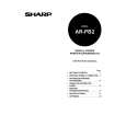
AR-PB2 10) Remove the securing screws holding the P side OP cover in the rear lower cover which was removed in the step 2, then remove the P side OP cover. Next, paste an attached label at the position only for Sweden and Norway as shown in the illustration.
P side OP cover
Wire saddle
Label Securing screws
Printer relay cable
(2) Expansion memory installation
a. Memory expansion in the printer control PWB 11) Hook the rear lower cover on the securing screw 4 which was loosened in the step 1 as shown in the illustration. Next, tighten the securing screws 1, 2 and 3 temporarily, which were removed in the step 2 and tighten the securing screw 4 which was loosened, tighten the securing screws 5, 6 and 7. Reinstall the rear cover tighten (which was removed in the step 2) to the original position by putting it onto the securing screws 1, 2 and 3 which temporarily secure the rear cover, then tighten the securing screws 1, 1 and 3 after tightening the securing screws 8 and 9.
Securing screw
Normally there is no need for memory expansion. However, memory expansion will increase the printer performance. When printing graphics or complex data, memory expansion will increase printing speed. Memory of 16MB or 32MB can be installed to the two slots. (16MB onboard) Different capacity of memory can be installed to the two slots. The total memory after expansion may be 32, 48, 64, or 80MB. After the above procedure, select VM Option menu and set the total memory capacity. b. ICU PWB memory expansion The copier ICU PWB requires total memory capacity of 16 (20)MB or more. Memory of 16MB or 32MB can be installed to the two slots. (4MB onboard) Different capacity of memory can be installed to the two slots.
Rear cover
Loosened screw Rear lower cover Securing screws
B. Stand-alone environment (Printer (parallel) cable connection)
Plug the connector of the Centronics cable (sold separately) into the Centronics port on the printer box base.Plug the other connector into the laser printer port on a personal computer.
12) If equipped with the RADF/ADF/SPF, reinstall the connector that was removed in the step 2 to the original position on the main copier unit, then secure with screws attached to the connector.
Connector going to the laser printer port on the personal computer
Centronics cable (sold separately)
Screw Connector
1 Connect the printer relay cable to the connector of printer box. 2 Attach the packaged wire saddle to the printer relay cable. 3 Insert and attach the wire saddle at the position of rear lower cover as shown in the illustration.
3�3
 $4.99 ARPB2 SHARP
Owner's Manual Complete owner's manual in digital format. The manual will be available for download as PDF file aft…
|
|
|
> |
|