|
|
|
Categories
|
|
Information
|
|
Featured Product
|
|
|
 |
|
|
There are currently no product reviews.
 ;
Complete MFG Service Manual at a good price FAST !
;
Downloaded the manual, reasonably straightforward, pretty much exactly as advertised.
 ;
very helpfull
circuit diagram and sparepart list available
;
Very good reproduction (copy) of original manual. Didn't have a parts list, but schematic was completely labeled with parts. Complete instructions on how to adjust mechanical functions of the 8-track deck. Well worth having and at a very reasonable cost.
;
It's a full manual. All the parts are in there. I haven't found the problem yett, but I am working on it; hope I can rebuild the part myself. To make it more secure and unbreakable this time. Because the part has failed several times before and costs a lot to let it be repaired.
Thanks so much for this rich illustrated and parted manual.
AV21BJ8ENS AV21BJ8EPS AV21BJ8EES AV20BJ8EES
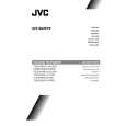
SPECIFIC SERVICE INSTRUCTIONS
DISASSEMBLY PROCEDURE
REMOVING THE REAR COVER
1. Unplug the power c ord. 2. Remove the 5 screws marked A as shown in the Fig. 1. 3. Withdraw the rear cover toward you.
CHECKING THE PW BOARD
To check the back side of the PW Board. 1) Pull out the PW Board. (Refer to REMOVING THE MAIN PWB). 2) Erect the PW Board vertic ally so that you c an easily check the back side of the PW Board. [CAUTION] " When erecting the PW Board, be c areful so that there will be no contacting with other PW Board. " Before turning on power, make sure that the wire connector is properly connec ted. " When conducting a check with power supplied, be sure to c onfirm that the CRT EARTH WIRE (BRAIDED ASS�Y) is connected to the CRT SOCKET PW board.
REMOVING THE MAIN PWB
" Removing the rear cover. 1. Remove the screw marked B as s hown in the Fig.1. 2. Slightly raise the both sides of the chassis by hand and withdraw the MAIN PWB backward. (If necess ary, take off the wire clamp, connectors etc.)
REMOVING THE SPEAKER
" Removing the rear cover. 1. Remove the 4 screws marked C, and remove speaker as s hown in Fig. 1.
WIRE CLAMPING AND CABLE TYING
1. 2. Be sure to clamp the wire. Never remove the c able tie used for tying the wires together. Should it be inadvertently removed, be sure to tie the wires with a new c able tie.
REMOVING THE FRONT AV JACK PWB
" Removing the rear cover. " Removing the rear MAIN PWB. " Removing the FRONT CONTROL PW B 1. Remove the 2 screws marked D. 2. Remove the FRONT AV JACK PWB.
REMOVING THE HP JACK PWB
" Removing the rear cover. " Removing the MAIN PW B 1. Remove the 1 screws marked E . 2. Remove the HP JACK PWB
6
No.51998
|
|
|
> |
|